
By Peter Kreussel
Spational models start life as wire frames. After you add textures and lighting, they can be converted to artificial 3D scenes. This process is known as rendering. Most industrial designs, from cars to coffee machines, are created using this method.
Blender is an open source program that handles all the steps from the construction of a model, through texturing and lighting, to rendering the 3D scene. Blender also has powerful animation features. This article describes how to build a basic 3D model using a cartoon character as a reference. Next month, I'll describe how to teach this static model to walk.
There is no need to install Blender in the traditional sense of the word. Just download the archive from the Blender homepage [1], and move the Blender directory to a suitable location in your filesystem. Then copy the .blender subdirectory to your home directory. Your machine is now set up for 3D modeling.
To make things simpler, we will be using a second program in this workshop: the vector graphics program Inkscape [2], which we need to create curves as the basis for constructing 3D shapes. Although you can draw curves directly in Blender, it is much easier to use Inkscape. Blender can import Inkscape's SVG format directly. Most current distributions include Inkscape, and if yours doesn't, you will find a static RPM at [3]; the only critical dependency for the RPM is GTK 2.4.
Launch Inkscape and select the freehand drawing tool by pressing [F6]. You can change the zoom factor by turning the mouse wheel, and the middle mouse button moves the current view section. Figure 1 shows a sketch of a cartoon character that we will be converting into a 3D model.
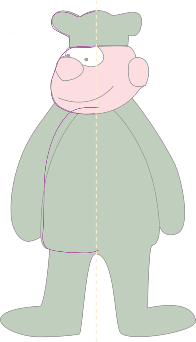
Using Figure 1 to guide you, draw the contour of the left half of the man's hat. Press the [Shift] key and hold down the left mouse button while doing so. You can stop drawing by letting go of the mouse button, and you can just start drawing again where you left off - this makes it easier to draw longer lines. When you are finished drawing the hat, follow the same steps to draw the head and body of the figure. When you are drawing the body, note that the drawing in the background does not give you the actual shape, as the arms cover part of the body. The magenta line in Figure 1 shows you the shape of the body underneath the arms.
You don't need to be too exact with the drawing. Just select the lines you have drawn, and press [Ctrl]+[L] repeatedly, to tell Inkscape to smooth the lines. Then press [Ctrl]+[A] to select the whole drawing, drag the drawing to the top left corner of the page, and store your work.
Now it's time to launch Blender. The program always runs in full-screen mode, without a window titlebar. It comes up with a standard scene that shows you a cube at the center of the screen. Now press [X]; Blender will prompt you to Erase selected?. Press [Enter] to confirm and to remove the cube. Select File | Import | Paths in the menu at the top of the screen. In the dialog that then appears, select Inkscape (.svg). Open the svg file with the outline of the cartoon character in the file browser. The Select Size menu now appears on your screen. Select Scale on Width. Then use the mouse wheel to change the zoom factor until the outline fills the screen. Press [Ctrl]+[4],[6],[8], and [2] in the numeric block, if needed, to adjust the view.
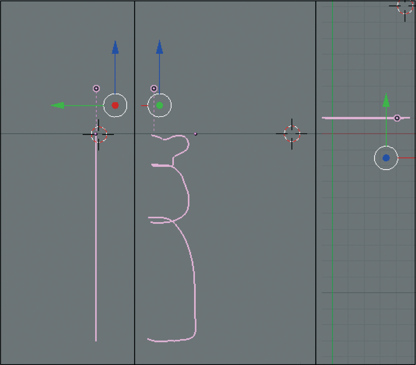
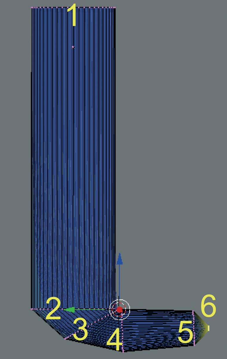
When you launch Blender, the program gives you a bird's eye view of the scene. The imported character will be lying flat on the floor. Of course, we want the figure we will be constructing to stand up. To rotate the figure, first move the cursor to the bottom end of the curve. Pressing [1] in the numeric block enables a frontal view. All you can see of the figure is a straight line. Make sure that the cursor is located on the right edge of the line in this view. Whenever you move the cursor, or another object to a specific position in 3D space, you always need to check the results from two different perspectives (Figure 2).
Drag the mouse pointer a few centimeters below the cursor. Press [R] (for rotate) and [X] (to rotate about the X axis) to rotate the curve until the cartoon character stands upright. To do so, rotate the line that extends from the mouse pointer exactly 90 degrees to the left and click with the mouse. Now press [Alt]+[C], and then [Enter]. This tells Blender to convert the curve to a mesh type object. Curve objects imported from Inkscape as vector graphics always need converting to let Blender change them into 3D objects.
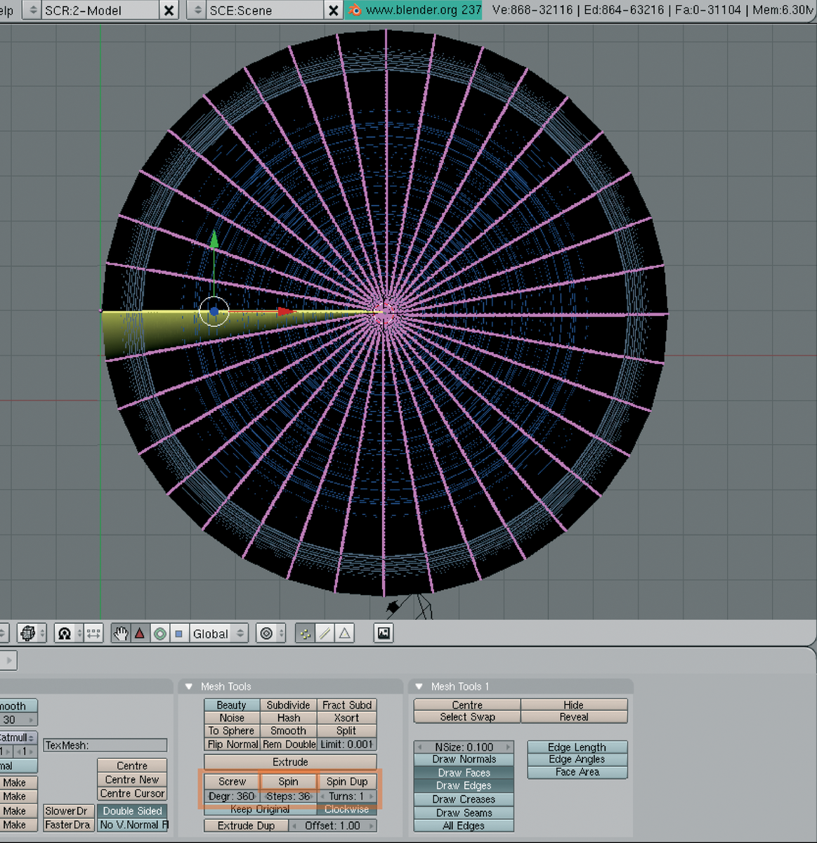
To convert the profile into a 3D object, we now need to rotate it about an axis through the two endpoints. We left the cursor marking the position of the axis of rotation at the right position in the last step. Blender always rotates curves parallel to the drawing area. Change to the bird's eye view again by pressing [7] in the numeric block. Then press the [Tabulator] key to switch to Edit mode, where you can change the properties of the selected object in the lower third of the window. [A] selects all the points in the line; they should be highlighted in yellow. Now click Degr: (Figure 3), hold down the mouse button, and drag the mouse to the right until a value of 360 appears. This tells Blender to rotate the selected line through a full 360 degrees. Follow the same procedure for the Steps: box, until the value changes to 36. Clicking on Spin then creates the hat, head, and body of the character (Figure 3). Now press the [Tabulator] key again to quit Edit mode. Blender now shows you the complete "spin machine object" with a shaded surface. In front view ([1] in the numeric block) you should see the hat, head, and body of the figure.
We can base the arms on a circle. To create the circle, move the cursor to the right of the torso in the front view ([1] in the numeric block). Then select Add | Mesh | Circle in the menu at the top of the screen. This tells Blender to create a circular figure and change to Edit mode. Press [A] to unselect the current selection. Place the 3D cursor in the center of the circle, move the mouse pointer a few centimeters to the right, and press [A] to select all the points on the circle. Then press the [S] key. Drag the mouse to scale the circle until the circumference of the arm matches the figure (Figure 4). Make the change permanent by clicking with the mouse. Then press [R], [X] to rotate the circle parallel to the drawing area, so that just a single line is visible.
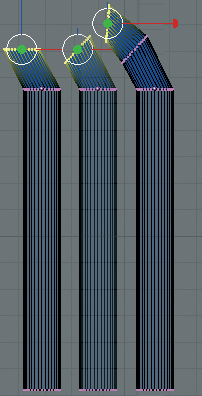
Press [E] to extrude the circle, select Only Edges, and then, in the pop-up that appears, move the copy of the circle down until the "tube" is the right length for the straight part of the arm. [A] unselects the current selection. Press [B] and hold down the left mouse button to drag a selection box. Use this to select the circle that delimits the top of the arm. Then press [E], click on Only Edges, and extrude the circle slightly toward the top left in the pop-up that then appears (Figure 4, left). Click with the mouse to fix the circle in position. To create a bend, you now have to rotate the top cross-section. To do so, drag the mouse a few centimeters past the selected arc, and press [R], and then [Y]. Use the mouse to rotate the cursor through 45 degrees (Figure 4, center). Extrude the cross-section again, and rotate again as described previously to create the next arm section (Figure 4, right). This completes the left arm. Press [Tab] to quit Edit mode. Then press [G] to move the arm to the right position.
Working in Object mode, you can select, scale, move, and rotate single or multiple objects by right clicking. In contrast to Edit mode, you can't change the shape of the objects. Create a duplicate of the arm by pressing [Shift]+[D]. Press [G] and then [X] to move the duplicate to the left, along the X axis, past the upper torso. To flip the duplicate, place the cursor in the middle of the top cross-section. Press [Ctrl]+[M] and select X Local to flip the arm, which you can then move to the right position by pressing [G], [X].
You can use extrusion to create the legs. In front view ([1] in the numeric block) move the cursor to a position to the right of the torso, and select Add | Curve | Bezier Circle to create an arc. Then quit Edit mode ([Tabulator]) and press [R],[X] to rotate the arc parallel to the floor of the virtual scene. [Alt]+[C] converts this into a mesh object. You can then press [S] to scale the object to the right size for a leg (Figure 5, cross-section 1). [Tabulator] takes you back to Edit mode, where you can press [A] to select all the points on the mesh line. Press [E] and click Individual Faces to start extruding. Now move the cross-section down until you are through the length of the legs (Figure 5, cross-section 2).
To model the bend of the feet, first rotate the view through 45 degrees by pressing the [4] key in the numeric block 6 times. Then place the cursor at the right end of the bottom cross-section. Press [E] and select Individual Faces, then press [R]. You can now rotate the new cross-section through 45 degrees about the cursor. In contrast to the legs, the foot cross-section is oval. Compress the selected circle outline by pressing [S], [Z] (scale in the direction of the Z axis) to about two thirds of its original size (Figure 5, cross-secton 3). Extrude and rotate again until the arc this creates is standing upright (Figure 5, cross-section 4). Again scale down to about two-thirds. Now extrude the flat part of the foot without rotating (Figure 5, cross-section 5). You will need to scale the cross-section down to about two thirds again. Finally, after extruding by a few millimeters, first press [Shift]+[S] and select Cursor -> Selection to move the 3D cursor to the center of the selected cross-section. Then press [S] to set its size more or less to zero (Figure 5, cross-section 6). This completes the leg. After quitting Edit mode, move the leg to the right position. If you press [1] in the numeric block to toggle to front view, you will probably have to move the leg in the direction of the X axis to allow it to sit on the right side of the upper torso. [Shift]-D duplicates the leg, and you can then press [Cursor left] to move it to the right position. You have now completed the figure, and you have learned a lot about extruding in the process.
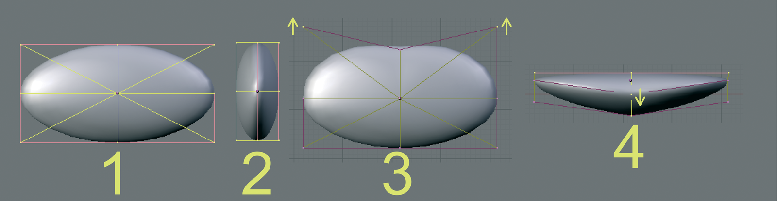
It's time to design the face. We need so-called NURBS surfaces for this process, objects whose surface can be manipulated by tweaking handles outside of the object. Place the cursor next to the head and select a sphere: Add Surface | NURBS Sphere. Move the cursor over the sphere, and extend the sphere laterally by pressing [S], [X]. Press [4] in the numeric block 6 times to rotate the view to the side, and flatten the sphere from this perspective until you have a flat lens ([S], [Y]). Change to a front view of the image ([1] in the numeric block), and press [A] to unselect. Then press [B], and use the selection box to select the small pink handles on the right edge of the guides.
Again press [B], and hold down the [Shift] key while you select the top right handle. Press [G] and move both slightly upward. The curves of the top part of the circle are now nearly rectangular. Press [7] in the numeric block to view the object from the the top.
Enable all three handles in the middle, and additionally the left and right lower handles. Then drag the selection slightly down to create a curve.
The lens-shaped surface can now be dropped onto the face. To do this, quit Edit mode, change to front view, and drag the object to the right position. Then change to the side view, drag the new component close to the head, and hover the cursor over it. Press [R], [X] to tilt it slightly, and then push it about a third of the way into the head (Figure 6). The pupils are spheres, which you can add by selecting Add | Mesh | UVSphere; then scale down, and move the spheres to the right position. As always when you move something in a 3D space, check the front and side views to ensure that the eyes are in the right position.
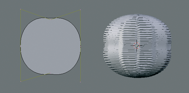
Now change to the side view to create the ears. Move the cursor to a position to the right of the head. Insert a NURBS circle (Add | Curve | NURBS Circle), and scale the circle to the right size. Then press the right mouse button and hold down the [Shift] key to select the top two handles; press [G] and drag the handles slightly upward. The upper top half of the circle should approach the shape of a square. Do not drag the handles so far as to create a "B" shape (Figure 7). Repeat this with the lower two handles, and then quit Edit mode. Change to front view by pressing [1] in the numeric block. [Alt]+[C] converts the curve into a mesh object. [Tabulator], [A] then enables Edit mode again and selects the points on the line.
Press [E] and select Individual Faces to change the line into a flat disk. Enable all the points on the mesh by pressing [A] twice. Mesh | Edges | Subdivide Smooth creates a slight curve on the right side of the disk. Leave the Percentage value at 100 percent. Then quit Edit mode. Tilt the ear slightly to the left to match the shape of the head, and drag it into position. Make sure the ear is in the right position from the front and side perspectives. Duplicate the ear by pressing [Shift]+ [D]. Place the cursor in the middle of the ear; then press [Strg]+[M] and select Z Local to flip the ear, and position the second ear.
The nose is a simple circle, which you can add to the drawing by selecting Add | Mesh | UVSphere. In the two pop-ups that follow, enter a value of 16 for Segment and Rings. Scale the circle down to the right size for a nose (see Figure 10) and use the front and side views to position the nose so that about half of the nose disappears into the face. Press [A] in Edit mode to unselect the current selections. Then change to front view, and right click to select the top point on the circle. Enable Proportional Editing in the Mesh menu at the lower edge of the drawing area, and select Sphere in Proportional Falloff. Then, in side view, press [G] and drag the selected handle to the top and right to lengthen the sphere. Proportional Editing means that changing one handle affects the neighboring points. falloff specifies how the effect lessens the farther away you get from the source. The Sphere setting gives you rounded forms when moving. Unfortunately, the whole sphere moves in the direction of the point that you moved, and you will need to reposition the nose. This completes the 3D model of the cartoon character apart from one minor item. Press [A] to select all objects. They should be highlighted in pink; if not, press [A] again. Then in the lower third of the screen, in the area below the Mesh heading, set both text fields in the Subdiv: line to 2; click the field and drag the mouse to the right. Now click SubSurf to tell Blender to smooth the surfaces. The arms are now rounded like in the finished rendering object (Figure 10).
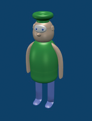
Before we can render our little hero, we need to set up the camera position and lighting, just like in a real movie take. Press [7] in the numeric block to switch to the bird's eye view; this gives you a better overview of the scene. Then, if needed, adjust the zoom factor until the camera becomes visible bottom right, and select the camera by right clicking. Next, change to the camera perspective by pressing [0] in the numeric block. The middle frame shows you a frame from the rendered scene. Move the cursor to the top, right corner of this frame, and drag the mouse down and slightly to the left. Press [S] to use the mouse to adjust the distance to the camera. Set the camera up so that the character fills most of the frame. If you now press [G], you can move the camera to leave the figure at the center of the frame. Pressing [R], [Z] gives you the ability to rotate the screen until your cartoon character looks you in the eye. A slightly off-center perspective is preferable to a head-on shot (see Figure 10).
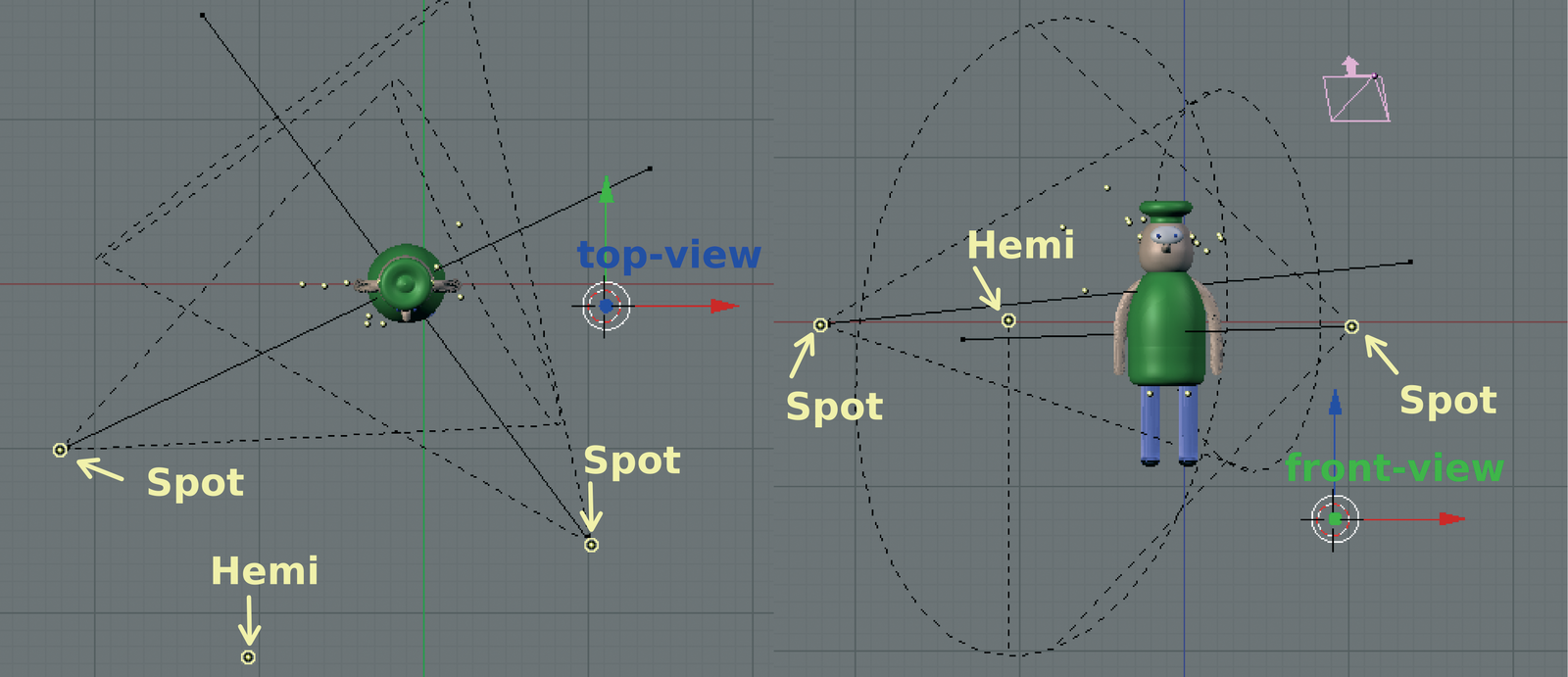
Now you need to apply lighting to the figure. To do so, first change to the bird's eye view. Then select Add | Lamp, as shown on the left of Figure 8, to add two Spot lamps and one Hemi lamp. Switch to front view to ensure that the lamps are all about level with the figure's chest, and move the lamps if needed. To set up the lighting as shown in Figure 8, you need to scale the lamps once they are in position, and turn them to face the right direction.
The virtual scene is now ready for a snapshot. Press [F12]. The image that Blender now renders in a new window should resemble the finished item in Figure 10, apart from the colors. The final step is to define the colors. Select a part of the graphic you imported from Inkscape (hat, head, and torso) and switch to Edit mode. Then press [B] and select the hat. [P] isolates the hat from the rest of the figure. Repeat this process for the head, and then quit Edit mode. You can now select the hat, the head, and the torso as individual objects.
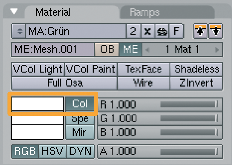
Select the hat first. Press [F5] to display Shading mode in the lower third of the Blender screen. The square area below Preview shows the surface properties in standard lighting. You can set the color by clicking the color square next to the Col button (Figure 9). Use these steps to set colors for the individual parts of the figure. When you are done, press [F12] to render the figure again, but in color this time.
This completes the phases of 3D modeling, from an outline, through a 3D mesh, to a rendering of the 3D scene. A 3D model is much more than a drawing. You can view the model from any angle. If you place the model on a surface, it will cast a realistic shadow. And last but not least, you can move the model and record these movements to create a movie. I will discuss animation in part 2 of this series in next month's issue.
If you are interested in becoming better acquainted with Blender, you might like to download the Blender documentation from [4]. The numerous Blender-related communities are a good place to look for more tips [5].
| INFO |
|
[1] Blender homepage: http://blender.org
[2] "Inkscape: Vector Graphics with Inkscape," Linux Magazine 7/2005, pg. 82. [3] Inkscape download: http://www.inkscape.org/download.php [4] Blender documentation download: http://download.blender.org/documentation/BlenderManualIen.23.html.tar.gz [5] Community overview: http://blender.org/cms/Websites.7.0.html |