By Peter Kreussel
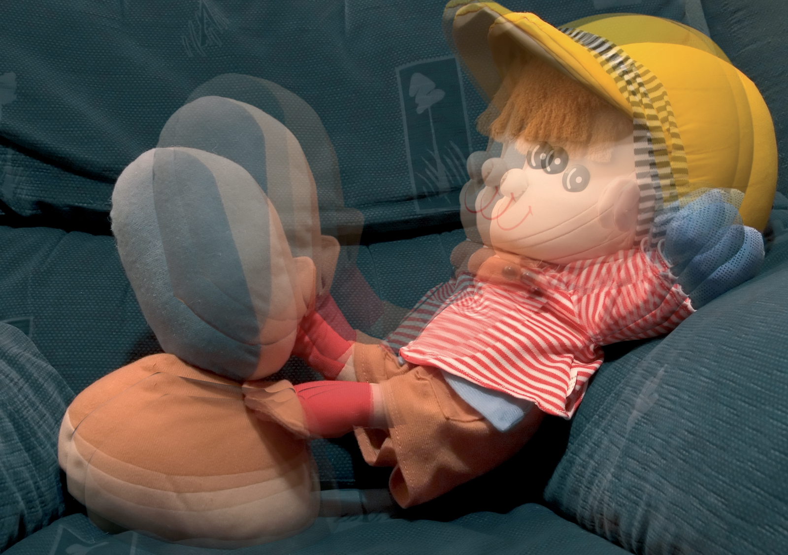
Character animation - the art of bringing virtual characters to life - is the computerized counterpart to the hand-drawn cartoon. Replacing the drawing board with the computer does not really change the craft. Computer-generated animations still benefit from a realistic look and feel. Blender is capable of producing photorealistic images, and Blender offers some benefits that conventional cartoonists will never enjoy. For instance, objects in a Blender scene "interact" autonomously, and Blender correctly calculates the highlights and shadows when 3D objects change their positions (Figure 1).
Last month we showed you how to create a 3D image in Blender. This month, we'll show you how to put an image in motion using Blender's animation tools.
Blender includes powerful tools for generating motion pictures. These tools work with so-called key frames: in other words, there is no need to generate every single image in a video sequence. For example, you could specify the position of an object in the first and tenth frames. Blender will then automatically calculate the intermediate steps, thus considerably reducing your workload.
Floating rotating objects across the screen, and changing the colors and sizes of these objects, might be a nice effect for the intro to a news broadcast, for example, but this is not what I would call character animation. After all, we don't just want to beam our figure across the screen. We want its legs to move when it crosses the screen; and we want to see those knee joints bend. Thus, character animation not only means rotating and moving an object, but specifically changing the shape of the 3-dimensional object. If you bend a hose, this has an effect on the diameter. Although this is not very flattering for humans, the principle is the same for the skin and flesh that covers our bones when we move our arms and legs.
Again, Blender just imitates Mother Nature: the program uses a "skeleton" (Armature) of bones and joints as the basis for moving figures. You can move the bones just like moving a puppet. Blender treats the limbs like elastic objects and changes their shape to match.
You can download Blender from the Blender website [1]. We will be using the latest version of the program for the remaining steps in this tutorial; after all, animation functions are far quicker in this version. As Blender uses OpenGL to display wire frames, you will need to ensure that your graphics adapter supports 3D acceleration.
The following steps assume you are familiar with basic steps such as zooming views, and selecting objects in Blender. If you are not familiar with Blender, you might like to read the first part of this tutorial in last month's Linux Magazine.
3D animation is a computationally expensive process. Even a very small film clip may contain 20 frames, which means that Blender has to recalculate the scene 20 times. Before you launch into the animation, you should simplify the wire model. To do so click the Editing button in the lower third of the screen (Figure 2, item 1), to display the Editing panel for object manipulation. Press [Z] to toggle between the wire frame and the solid view. The wire frame is typically preferable, as it is quicker. You also need to ensure that you are working in Object Mode and not in Edit Mode.
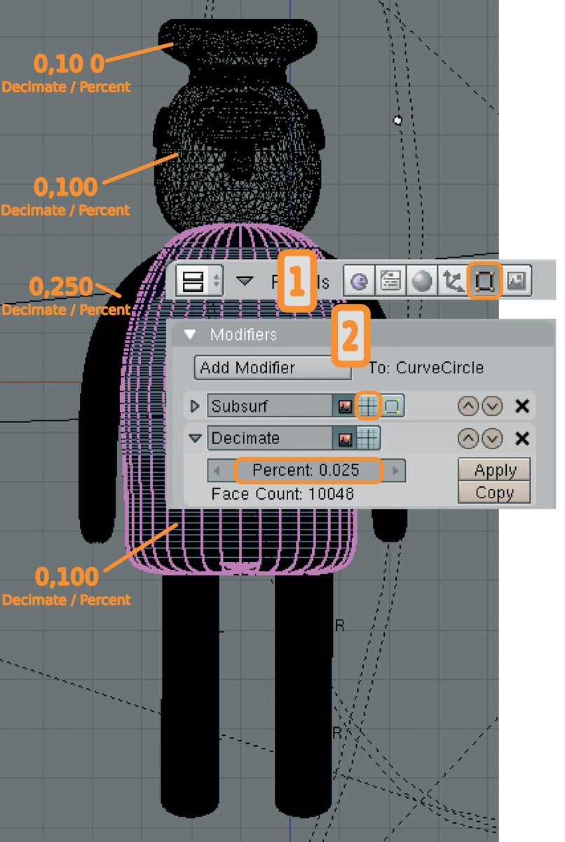
The Editing panel was reworked in Blender 2.40. Many functions that were confusingly grouped under Mesh in former versions our now more logically grouped under Modifiers. Surface smoothing (Subsurf), which we enabled for most of our objects in part one of this tutorial, is now also grouped under Modifiers.
Start by selecting the cap, then disable the highlighted button to the right of Subsurf, shown in Figure 2, item 2. This disables the individual wire frame element view but without influencing the final rendering results. However, this will definitely speed up the preview. Now click Add Modifier and select Decimate in the drop-down menu. In the Percent: field, set the value of 0.100, and click on Apply. Wait for Blender to catch up (that is, wait until the buttons change color when you hover the mouse over them), then press the button again, and say OK when prompted by Blender. Repeat this procedure for all objects for which a value for Decimate / Percent is shown in Figure 2. Disable the preview of the surface elements (Figure 2, 2) for the other objects with a Subsurf entry in Modifiers.
Position the cursor as shown in Figure 3. Check the position from the front and side perspectives. Press the space key and select Add | Armature from the menu. Then press [G] and drag the mouse to move the endpoint of the "bone" you have just added to the position of the knee (in the middle of the leg). Now press [E] for extrude to add a second bone. Move the bone to a position that makes anatomic sense. Then press [A] twice to select both bones. [Shift]+[D] creates a copy which you can now drag to the other leg using the mouse.
Again press [A] twice to select all four bones. Enable the buttons Draw Name and X-Ray in the middle of the Armature area at the bottom of the Blender window. Blender will now show you the names of the bones, Bone through Bone.003. To make things easier, you might like to assign more intuitive names. If the list of bones does not fit in the display window, you can drag the border of the lower panel slightly upwards. Let's call the bones ul for "upper leg" and ll for "lower leg". Add .L or .R for left or right (Figure 4). The convention of tagging symmetric objects as .L and .R is a requirement for automatically mirroring bone positions, which we will have to do later.
This completes the bone structure for the legs, but attempting to move this would have no effect whatsoever on the rendering results. Bones are just auxiliary objects in Blender; all they do is define the movements and deformations of the wire frame that surrounds them. For this to happen, you have to tell Blender which areas of the surrounding 3D object are "driven" by moving the bones. This process is referred to as skinning, as what you are doing is pulling a virtual, flexible skin over the bones. We want the tube-shaped legs to bend at the knees when the figure walks, and we want them to change shape to reflect this. So we need to tell Blender which areas of the 3D object are connected to which bones.
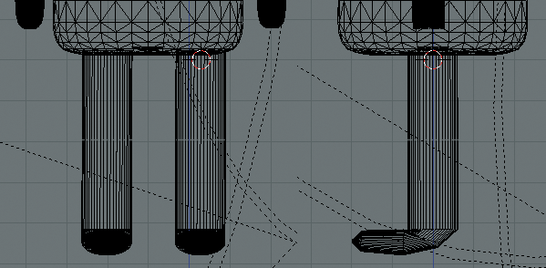
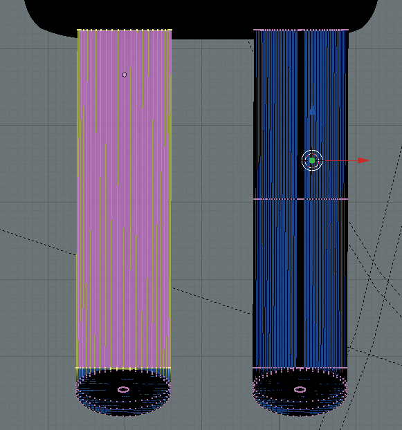
Up to now the legs have been made up of a single tube. To be able to assign the top half of the leg to the upper leg bone, and the lower part to the lower leg bone, we will first need to divide the legs. As the legs always move at the same time, it makes sense to group them to form a single object before we do so. Select the left leg by pressing the right mouse button, then hold down the [Shift] key and add the right leg. Pressing [Ctrl]+[J] groups the two objects. Press the [Tabulator] key to enable Edit Mode. If you see bright yellow dots, disable them by pressing [Ctrl]+[A]. In the lateral view, press [B] and drag a selection frame over the top and lower leg cross-sections (Figure 5, left). Then select Mesh | Edges | Subdivide in the menu at the lower edge of the drawing area. A ring of new handles divides the leg at the position where we need the knee joint (Figure 5, right).
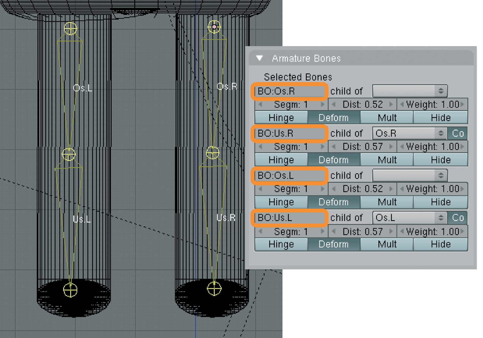
Now quit Edit Mode. Ensuring that the wire frame for the legs is enabled, press the [Shift] key, and select the bones. A single click is all you need, as the four bones are just sub-elements of the same object. Press [Ctrl]+[P] and select Armature in the Make Parent pop-up; then select Create From Closest Bones in the Create Vertex Groups ? menu. The Vertex-Groups represent the upper and lower leg bones for both legs, which can be moved separately. Now press [Ctrl]+[A] to deselect the current selection, and then select just the legs. When you enable Edit Mode, you will now find the names of the four bones in the Link and Materials area below Vertex Groups. Press [Ctrl]+[A] to deselect all highlighted, yellow points, and click on Select below the Vertex Groups. All the points that move when the Us.L, the lower left leg, is rotated now turn yellow. As you can see, automatic mapping of the wire frame points to the bones has not worked perfectly. Because our figure does not have an ankle joint, we have to move the foot along with the lower leg. Press [B] and select the missing points. Then click Assign to assign them to the lower leg bone. Press [Ctrl]+[A] to deselect, and then repeat these steps for the right leg and the Vertex Group Us.R.
You can now move the cartoon figure's legs. Quit Edit Mode. Just select the skeleton structure and change to the lateral view. Instead of Object Mode, select the Pose Mode entry in the list box for the Object menu. Select one of the lower leg bones, and press [G]. The knee should bend when you drag the mouse. Quit the rotation by pressing [Esc] on this occasion.
Our next target is to get the figure to run on the spot. We need four key frames to do this, where each frame represents one phase of the running action (Figure 6). Blender will calculate the intermediate steps automatically. In the first frame of the video sequence, we want the figure to stand just like in the first part of the tutorial. To select the current pose for subframe 1, first ensure that the field on which the current frame is based (Figure 6) contains a 1. Press [A] twice to select all bones, which should then turn blue. Then press [I] and select LocRot. This tells Blender to store the position and rotation data for the selected bones in frame 1.
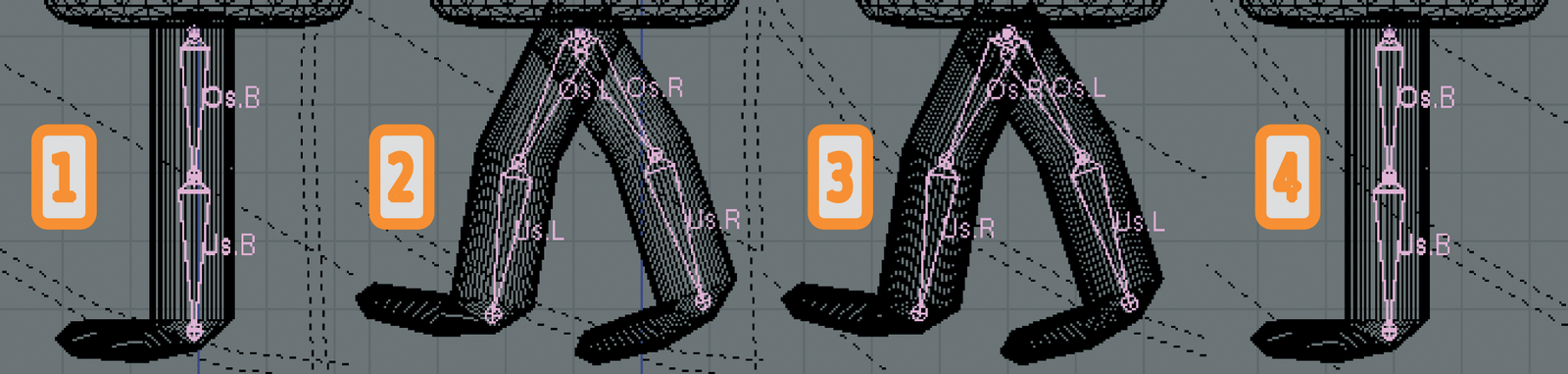
Now go to frame field 5. In frame 5 we want the cartoon character to move its left foot forward, its right foot back, and to bend its knees slightly, as shown in Figure 6. To allow this to happen, select the right upper leg bone in the front view. Position the cursors exactly on the upper leg joint. Press [R] to turn the leg slightly to the left to reflect the step position. Then enable the lower leg bone, press [R], and slightly bend the knee. Follow the same procedure to turn the other leg slightly to the left, and again bend the knee. Finally, enable all the bones and press [I] to store the position and rotation values.
The third pose, with the right leg forward and the left leg back, is an exact mirror image of the pose in frame 5, so there is no need to create it manually. To copy the pose, select the Copy Current Pose entry in the Pose menu, and then select frame 15. Now select Paste Flipped Pose. Ensure that all the bones are enabled and store the values by pressing [I].
In frame 20, we want the position of the legs to return to the starting position from frame 1. To allow this to happen, go to frame 1, and select Copy Current Pose. Then paste the pose into frame 20 by selecting Paste Pose, and press [I] to store. You can now go to frame 1 and press [Alt]+[A] to move the figure in the preview. The cursor shows which frame Blender is currently showing. [Esc] cancels the animation.
If we really want the figure to "run," of course, we have to move it through the scene. This is quite easy to handle with Blender; you just need to store different positions for the figure in frames 1 and 20. To do so, click on the drawing area and press [A] to select all objects. This makes the objects part of the figure and also selects the camera and the lamps. Press [Ctrl]+[left] and [Ctrl]+[right] to browse the various window layouts in Blender. Then press [Ctrl]+[left] to display an overview at the left edge of the screen. Hold down the [Shift] key, and click Camera and Lamp.001 through Lamp.003 to remove these objects from the selection. Pressing [Ctrl]+[right] takes you back to the normal window arrangement.
You need to find out how far the figure has to move for each step. To do so, go to frame 5 and zoom the display to leave just the feet visible. Then count the large and small boxes between the lower ends of the right and left lower leg bones. The figure will need to move twice as far as this with a single step forwards. Now select frame 1. The cartoon character is at the center of the screen right now. Press [0 XXX] in the numeric block to toggle to camera perspective, then press [G], [Y] and drag the character back to a position where the head is just about in view of the camera (indicated by the dotted outer frame). Press [I] and select LocRot to set the starting position for the first frame. Then go to frame 20. Press [G], [Y] and drag the figure to the left by the amount you ascertained previously. [I] and LocRot maps the position to the frame. Now, when you go to frame 1 press [Alt]+[A], you should see the cartoon character start "walking."
Time to render. Click the lower part of the window and press [F10] to display the Renderer panel. The settings for part one of this tutorial still apply. Rendering a sequence can take awhile. To gain a first impression, you might like to reduce the resolution and oversampling, which creates smoother surfaces during the rendering process. Then disable the OSA button in the Renderer area, and reduce the resolution by clicking on 25%. The sequence comprises just 20 frames, so we need a value of 20 in the End: field below the Play button. The big Anim button in the center of the lower window starts the processing. The cursor shows the number of the frame. You can tell that Blender has finished the animation when the cursor returns to normal, and the rendering window shows the last frame permanently. Close the rendering window and click Play to check out the results. Pressing [F9] in the lower third of the screen takes you back to the Editing panel.
Blender has already calculated the intermediate steps between the key frames (Interpolation). It is also possible to Extrapolate steps. This allows you to walk a character all over the screen without having to redefine the leg poses.
Press [Ctrl]+[left arrow] to enable the split screen mode, which we used to select individual elements in a list. This screen was specially designed for working with animations. Besides the object list on the left and a wire frame preview, you will find the IPO window (IPO stands for interpolation) on the right. This tool allows you to influence the way Blender interpolates and extrapolates motions.
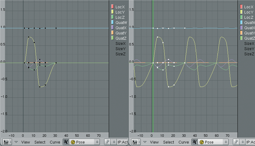
Enable the Armature in the object list. Set the two list fields below the Object Mode / Object windows to Pose Mode and Pose, respectively. Select one of the lower leg bones in the preview. The colored curves in the right window represent the object position and rotation of the bone. The X axis shows the elapsed time in frames; the Y axis shows the motion/rotation in Blender units.
You can use the mouse wheel to change the motion timescale and the middle mouse button to change the selection. Drag the mouse to the IPO window, and then press [A] to select all the points in the graph. Now, when you select Curve | Extend Mode | Cyclic in the menu below the window, all of these curves are extended cyclically throughout the whole window.
Set the value in the End: field to 100, and press [Alt]+[A] while hovering the mouse over the preview of the figure. The first 20 frames will look familiar. Then the forward motion stops but the legs keep on moving. The cyclical movement of the legs has been extrapolated and runs through all the frames, but the linear movement of the whole figure has not been extrapolated thus far.
Select the Curve.001 entry in the object list. Assuming a suitable zoom factor and display segment, you will see that the orange line shown as LocY (= position in Y direction) in the graph is first constant, before dropping between frame 0 and 20, and then becoming constant again. This reflects the movement of our cartoon character, which starts at frame 0 and stops at frame 20. Press [A] while hovering the mouse over the IPO window. Then select Curve | Extend Mode | Extrapolation in the menu below the window. The orange LocY line then drops continuously throughout the whole coordinate system. Use this technique to extrapolate the movement of all objects apart from World, Camera, and Lamp.001 through Lamp.003. Select Object Mode/Object for both windows for the Armature object this time. We created the stepping motion of the legs in Pose Mode, however, the linear motion of the figure was defined in Object Mode. Blender supports two different animation systems here.
Now we can set up the last frames to allow the figure to move completely out of the scene. [F10] takes you to the rendering controls. Select the directory where Blender will store the completed animation in Output. By default Blender stores the frames as individual jpeg images. You can change this in Format on the lower left, by selecting AVI Jpeg instead of Jpeg.
Our cartoon character can move its legs, but apart from that, it looks pretty stiff. The animation techniques we have looked at in this article will help you extend the figure's locomotor system (you could move the arms to match the legs, and teach the figure to nod its head, for example). Professionals use similar techniques when they design the bones and joints of their characters in Blender to imitate facial expressions.
If you are in need of some inspiration after all the hard work, check out the Internet page, where the Pixar team describes the development process that led to "Toy Story 2" [2].
| INFO |
|
[1] Blender download: http://www.blender.org/cms/Blender.31.0.html
[2] Pixar on "Toy Story 2": http://www.pixar.com/howwedoit/index.html |