By Carsten Zerbst
Today's PCs have the processing power to handle 3D images that once required expensive Silicon Graphics workstations. The world of 3D programming is therefore open to almost anyone. The OpenGL developers provide a substantial C API, but thanks to Paul Obermeier's new Tcl3D extension [2], getting started with OpenGL has become even easier. Tcl3D offers access to OpenGL commands in TCL.
Brian Paul developed his OpenGL widget Togl shortly after OpenGL was first released. However, Tcl developers had to use C to write any functions they needed for creating or lighting models. Tcl3D removes this need, giving scripts access to the lion's share of the OpenGL API. Tcl3D even supports extensions such as OpenGL 2.0, the Nvidias CG Shader library, or SDL joystick support [4].
To install Tcl3D, you need the Tcl interpreter, an OpenGL library, and possibly CG and SDL. OpenGL is available as a software only implementation, Mesa [5], or with hardware acceleration to match your graphics card. Depending on the manufacturer, this can be an open implementation in the X11 driver or a proprietary variant, by ATI or Nvidia for example.
Tcl3D is easy to install. The homepage at [2] has both source code and prebuilt binaries for Linux. The current version is 0.3. In typical Tcl style, the extension can reside at any location on the filesystem, as long as the script adds this information to the path. This said, it is simpler to install the extension in one of the default paths. You will find them in the $auto_path Tcl variable.
Besides the Tcl3D library, it makes sense to install the package with programming examples. The package contains about 100 programs with useful suggestions for your own development work. If you are new to OpenGL, the redbook14 and NeHe directories are a good place to start. The former contains the examples from the legendary OpenGL Programming Guide [6], dubbed the Redbook because of its cover color, while the latter has the examples from the OpenGL Tutorial at [8].
OpenGL and the accompanying libraries contain over 300 commands that cover a full range functions for displaying 3D models comprised of coordinates, lines, triangles, and squares. The routines for spheres or cubes simply create the skin. If you need CAD style construction drawings, a CAD system, or the Open Cascade [9] CAD library are better suited to the task.
The Bluebook [7] describes the OpenGL API; the online version, or an older edition should be fine for most points. For the most part, Tcl3D uses the same command names as Tcl, and again for the most part, the way Tcl maps the C functions is self-explanatory: the documentation has precise details if you need them. The advantage of this approach is that examples from C programs are easily ported to Tcl.
You will definitely need good examples to get started, if you want to see more than an empty black window on your screen. Three dimensions give you more opporunity for errors. If you forget the lighting, or pan the virtual camera in the wrong direction, you see nothing.
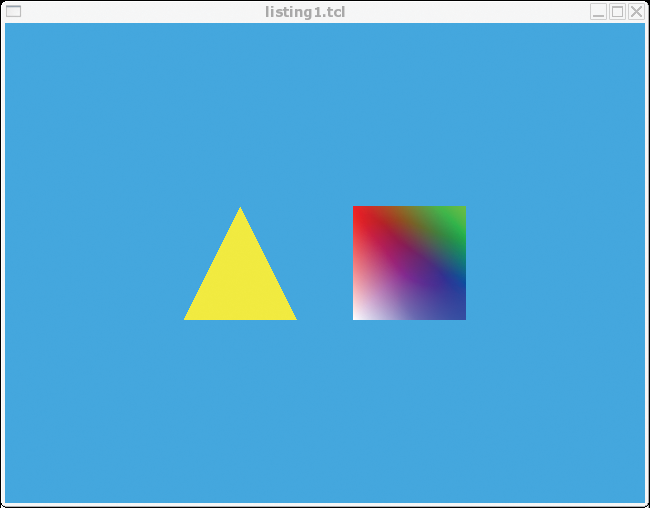
The code in Listing 1 creates the Hello World OpenGL example shown in Figure 1, a triangle and a square. Line 8 requests the Tcl extension. If Tcl3D is not installed in the normal path, Line 6 shows you how to modify the path. The 3D widget is then created by the togl command in line 71. The -width and -height options should be familiar from other Tk widgets; the OpenGL-specific options follow.
| Listing 1: Hello World in OpenGL |
01 #!/usr/bin/wish
02 # Simple Tcl3d example based on
03 # OpenGL Tutorial from http://nehe.gamedev.net
04
05 # Extend search path if needed:
06 #lappend auto_path /home/cz/tcl3d0.3
07
08 package require tcl3d 0.2
09
10 # Sets a few initial values, called when creating the window
11 proc tclCreateFunc {toglwin} {
12   glShadeModel GL_SMOOTH      ;# enable smooth color transitions
13   glClearColor 0.1 0.7 1 0.5  ;# define background color
14 }
15
16 # create and display 3D model
17 proc tclDisplayFunc {toglwin} {
18   # Delete color and depth buffers
19   glClear [expr {$::GL_COLOR_BUFFER_BIT | $::GL_DEPTH_BUFFER_BIT}]
20
21   # Set starting coordinates
22   glLoadIdentity
23   glTranslatef -1.5 0.0 -10.0
24
25   # Draw a red triangle
26   glColor3f 1 1 0
27   glBegin GL_TRIANGLES
28   glVertex3f  0.0  1.0 0.0
29   glVertex3f -1.0 -1.0 0.0
30   glVertex3f  1.0 -1.0 0.0
31   glEnd
32
33   # Square with different colored corners
34   glTranslatef 3.0 0.0 0.0  ;# restart
35   glBegin GL_QUADS
36   glColor3f   1.0  0.0 0.0  ;# First corner red
37   glVertex3f -1.0  1.0 0.0
38   glColor3f   0.0  1.0 0.0  ;# Second corner green
39   glVertex3f  1.0  1.0 0.0
40   glColor3f   0.0  0.0 1.0  ;# Third corner blue
41   glVertex3f  1.0 -1.0 0.0
42   glColor3f   1.0  1.0 1.0  ;# Fourth corner white
43   glVertex3f -1.0 -1.0 0.0
44   glEnd
45
46   # Display new model
47   $toglwin swapbuffers
48 }
49
50 # Calculate view for model,
51 # whenever window size changes
52 proc tclReshapeFunc {toglwin  b h} {
53   # prevent divide by zero
54   set h [expr {$h<1 ? 1 : $h}]
55
56   # Set Viewport
57   glViewport 0 0 $b $h
58   glMatrixMode GL_PROJECTION
59   glLoadIdentity
60
61   # Calculate and enable perspective
62   set angle 46
63   set perspective [expr {double($b)/double($h)}]
64   set von 0.1
65   set bis 100.0
66   gluPerspective $angle $perspective $from $to
67   glMatrixMode GL_MODELVIEW
68 }
69
70 # Draw window
71 togl .toglwin -width 640 -height 480 \
72   -double true -createproc tclCreateFunc \
73   -reshapeproc tclReshapeFunc \
74   -displayproc tclDisplayFunc
75 pack .toglwin -expand 1 -fill both
|
The -double option enables double buffering; that is, Open-GL draws a new image in the background first, and then replaces the screen image with the new one. This avoids flicker on drawing the screen. The -createprop, -reshapeproc, and -displayproc parameters pass in three Tcl procedures to the widget, which calls Createproc once on intializing, Reshapeproc on resizing, and Displayproc whenever it draws the screen.
The first procedure in Lines 11 through 14 is called tclCreateFunc. It initializes Open-GL; this is required just once per program run. One design principle is that settings apply until they need to be changed. If you have set the color for a shape to red, OpenGL will color every following object red, no matter whether the program inserts ten or ten thousand. The background color set by glClearColor in Line 13 thus applies to every screen.
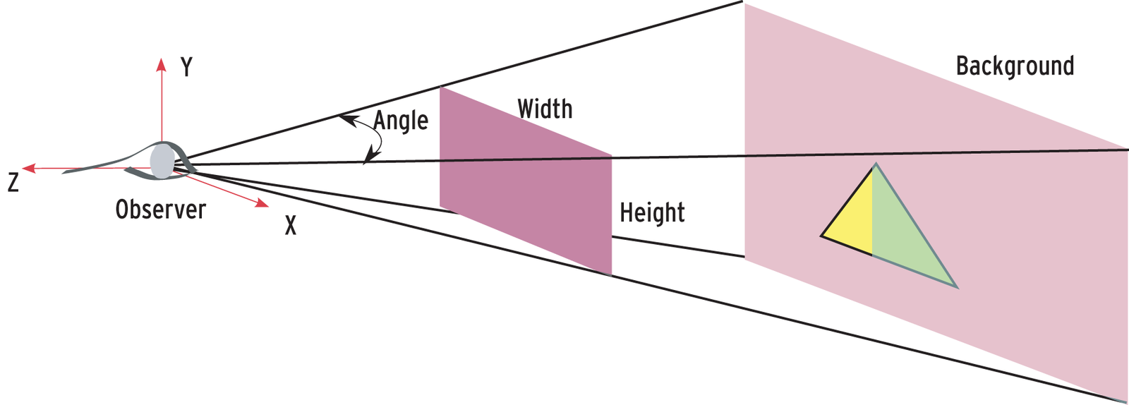
Next in Lines 17 through 48, the script defines the tclDisplayFunc. Tcl3D uses this callback whenever it draws the screen. After glClear has deleted the previous screen content in Line 19, the triangle and square are now drawn. At the same time, glLoadIdentity deletes the previous starting coordinates and the glTranslatef rotation, and sets new starting coordinates. The coordinate system is shown in Figure 2: the x and y axes describe the screen; the z axis adds depth.
Line 26 calls glColor3f to set the object color to red: the color values are taken from the RGB model, with values between 0 and 1 (additive colors red, green, and blue.) The block in Lines 27 through 31 then calls glBegin GL_TRIANGLES to define the first triangle with three vertexes through to glEnd. The script can specify multiple triangles between glBegin and glEnd.
Most surfaces can be depicted really well just using triangles, but OpenGL has other graphic primitives, such as points, lines, or squares. As an example, let's take a look at the square in Lines 34 through 44. After calling glTranslatef to define the starting coordinates, another coordinate list occurs between glBegin and glEnd. To draw a square, you need to make sure that all four points are on a single plane. If not, OpenGL will not display the square correctly, and gaps will occur in the geometry.
The square description also contains a color definition for each corner, causing OpenGL to draw a color gradient in the square. Now that the shape is completely defined, swapbuffers copies the image rendered in the background to the window, and the first OpenGL shape appears (see Figure 1).
The tclReshapeFunc function (Lines 52 through 68) is called when the widget is resized. It defines the model view. The OpenGL Utility library (Glu) provides a gluPerspective function to handle this. The view is known as a viewport (see Figure 2). The viewer is located at the starting coordinates and shows a section of the 3D model defined by the height and width of the window. The angle of 46° defined in Line 62 corresponds to the field of sight of the human eye.
The viewport only shows those parts of the model specified as being in view in Lines 64 and 65. In contrast to a photograph, the sections in front of or behind this sector are not out of focus but completely invisible.
Listing 1 has two major flaws. For one thing, the third dimension is invisible, as the viewer can only see the model from a single perspective. The second problem with the code in Listing 1 is the performance. The tclDisplayFunc procedure redefines the 3D model whenever the screen is redrawn. This may be fine for smaller models, but the sequence will be too slow, even with as few as 100 triangles.
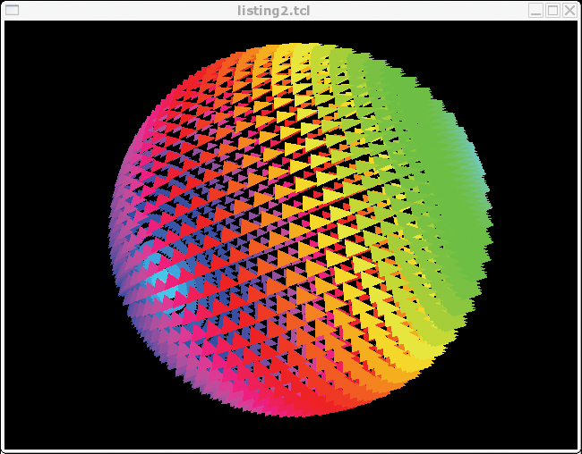
A second example that draws a sphere from about 2600 triangles (Figure 3) shows how to handle this issue. Redrawing the sphere would take far too much time. To avoid the need to do so, the tclCreateFunc procedure (Listing 2a) creates a display list. The list contains prebuilt geometries that the program can call as often as needed any time later. Using a display list improves the performance, as creating a shape can take 10 to 1000 times longer than displaying one, depending on the complexity.
| Listing 2a: Display List |
01 # Set starting values and create display list.
02 # Called when creating the window
03 proc tclCreateFunc {toglwin} {
04   # Black background
05   glClearColor 0.0 0.0 0.0 0.0
06
07   # Some tuning
08   glClearDepth 1.0
09   glEnable GL_DEPTH_TEST
10   glShadeModel GL_FLAT
11   glDepthFunc GL_LEQUAL
12   glHint GL_PERSPECTIVE_CORRECTION_HINT GL_NICEST
13
14   sphere 100 ;# Create display list once only
15 }
|
The sphere (Listing 2b) first creates a new display list and then fills it with triangles, in a way similar to the first example. Depending on the latitude, the triangles change color; the script uses the hls2rgb script to do this [12].
| Listing 2b: Create Sphere Model |
01 proc sphere {radius} {
02   set edge 10
03   set ::displayliste [glGenLists 1]
04   glNewList $::displayliste GL_COMPILE
05   for {set l 0} {$l <= 360} {incr l 5} {
06     for {set b -90 } {$b <= 90} {incr b 5} {
07       # Position in arc
08       set lr [expr {$l/180.0 * $::PI}]
09       set br [expr {$b/180.0 * $::PI}]
10       # Set color for next element
11       set hue [expr {sin($br/3.0)}]
12       eval glColor3f [hls2rgb $hue 1 1]
13
14       # Insert triangle
15       glBegin GL_TRIANGLES
16       glVertex3f \
17           [expr {$radius*cos($lr)*cos($br)}]\
18           [expr {$radius*sin($lr)*cos($br)}]\
19           [expr {$radius*sin($br)}]
20       glVertex3f \
21           [expr {$radius*cos($lr)*cos($br)}]\
22           [expr {$radius*sin($lr)*cos($br) +$edge}] \
23           [expr {$radius*sin($br)}]
24       glVertex3f \
25           [expr {$radius*cos($lr)*cos($br)}]\
26           [expr {$radius*sin($lr)*cos($br)}]\
27           [expr {$radius*sin($br) +$edge}]
28       glEnd
29     }
30   }
31   glEndList
32 }
|
| Listing 2c: Display Sphere Model |
01 proc tclDisplayFunc {toglwin} {
02   # Delete screen and depth buffer
03   glClear [expr {$::GL_COLOR_BUFFER_BIT | $::GL_DEPTH_BUFFER_BIT}]
04
05   # Set starting coordinates
06   glLoadIdentity
07   glTranslatef $::Posx $::Posy $::Posz
08   glRotatef $::Rotx 1.0 0.0 0.0
09   glRotatef $::Roty 0.0 1.0 0.0
10   glRotatef $::Rotz 0.0 0.0 1.0
11
12   # Call display list
13   glCallList $::displayliste
14
15   $toglwin swapbuffers
16 }
|
Instead of inserting the sphere at a specific position, the Tcl3D functions glTranslatef and gl-Rotat-ef set new starting coordinates and a new orientation (Lines 6 through 9). If the position and orientation variables change, the sphere moves to a different position. Instead of changing the position of the viewer, the script actually moves the whole model.
To interpret user interaction, the script uses Tk's binding technique in combination with callback functions. The callbacks react to mouse and keyboard events. Pressing the arrow keys moves the sphere. The scroll wheel changes the distance; holding down the left mouse button while turning the wheel rotates the sphere. The callbacks also call .toglwin postredisplay to force a redraw after completing the action.
Users interested in high resolution hard copy of their Tcl3D results can say thank you to Ian Gay for his tclgl2ps [10] project. The program creates genuine, scalable Postscript documents, thus giving users the ability to create high quality 3D hard copies.
3D models are mainly made up of triangles, which are easily and quickly created. However, it would take millions of triangles to emulate details such as eyes or clothing. Complex images can be applied to a 3D model using a process known as texturing. Recent graphics adapters typically have a huge memory for textures. Lighting applies the finishing touches. The standard lighting provided by OpenGL is about as attractive as neon light - but more pleasing light sources are available.
Even simple models that use just a few triangles can look quite realistic if you apply a suitable texture to them (Figures 5a through 5c). To allow OpenGL to mount the bitmaps to reflect the geometry, you need to provide specific instructions on what to put where.
This is where worlds collide: the three dimensional X-Y-Z coordinate system of the triangle, and the two dimensional S-T coordinate system used by the texture. The glTexCoord2f command tells OpenGL which part of the texture (S, T) to apply to the next defined geometrical coordinate (X, Y, Z).
Listing 3 shows the important parts of the source code. The main program inserts the tclCreateFunc function as -createproc into the OpenGL widget. The library then calls this function to create the content of the widget. The function loads the textures and creates the geometry.
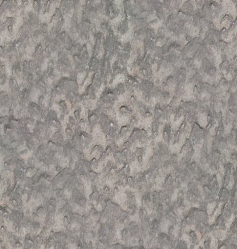
Bitmaps for textures are typically available on your hard disk, and realistic renderings will use photos of the required surfaces. Check out Mayang [13] for textures, or [14] if you are looking for woodgrains. Any bitmap will serve as a texture, however, the edge length should be a power of two, for example, 256 by 512. To avoid ugly looking seams, you can apply a Gimp filter to create a seamless pattern (Filters | Map | Make seamless).
| Listing 3: Textures |
01 # This is called once
02 proc tclCreateFunc {toglwin} {
03 # a few settings
04 glEnable GL_TEXTURE_2D
05 glEnable GL_DEPTH_TEST
06 glPolygonMode GL_FRONT_AND_BACK GL_FILL
07
08 # Load image in Tcl
09 if [catch {image create photo -file "worked_stone_8180226.JPG"} phImg] {
10 error "Error loading file: $phImg"
11 }
12
13 # Create OpenGL Vector with bitmap from Tcl image
14 set w [image width $phImg]
15 set h [image height $phImg]
16 set n [tcl3dPhotoChans $phImg]
17 set pTextureImage [tcl3dVector GLubyte [expr {$w * $h * $n}]]
18 tcl3dPhoto2Vector $phImg $pTextureImage
19 image delete $phImg ;# Bild aus Tcl löschen
20
21 # Specify interpolation
22 glTexParameteri GL_TEXTURE_2D GL_TEXTURE_MIN_FILTER $::GL_LINEAR
23 glTexParameteri GL_TEXTURE_2D GL_TEXTURE_MAG_FILTER $::GL_LINEAR
24
25 # Create texture from OpenGL vector with bitmap
26 set ::g_textureID [tcl3dVector GLuint 1]
27 glGenTextures 1 $::g_textureID
28 glBindTexture GL_TEXTURE_2D [$::g_textureID get 0]
29
30 if {$n == 3} {set type $::GL_RGB
31 } else { set type $::GL_RGBA}
32 glTexImage2D GL_TEXTURE_2D 0 $n $w $h 0 $type GL_UNSIGNED_BYTE $pTextureImage
33
34 # Delete OpenGL vector with bitmap
35 $pTextureImage delete
36
37 # Create display list...
38 set ::g_sphereDList [glGenLists 1]
39 glNewList $::g_sphereDList GL_COMPILE
40 # ...and fill with geometry and texture
41 renderSphere 0.0 0.0 0.0 1.5 $::resolution
42 glEndList
43 }
44
45 # Create sphere from triangles with texture
46 proc renderSphere {r p} {
47 [...]
48 # Normalenvektor berechnen
49 set normalX [expr {cos($theta2) * cos($theta3)}]
50 set normalY [expr {sin($theta2)}]
51 set normalZ [expr {cos($theta2) * sin($theta3)}]
52 glNormal3f $normalX $normalY $normalZ
53
54 # Simple cylindrical projection of texture
55 glTexCoord2f [expr {-1.0 * ($j/double($p))}] \
56 [expr { 2.0 * ($i+1)/double($p)}]
57
58 # Calculate coordinate positions
59 set posX [expr {$r * $normalX}]
60 set posY [expr {$r * $normalY}]
61 set posZ [expr {$r * $normalZ}]
62 glVertex3f $posX $posY $posZ
63 [...]
64 }
|
Unfortunately, there isn't a function to load bitmaps directly from disk in OpenGL; in fact, the process takes three steps. First, the script retrieves the bitmaps in typical Tk style using image create photo -file filename. Tk programs typically use this to load bitmaps for buttons. The if-catch construction in Lines 9 through 11 issues an error message if the script fails to load the file.
Next, the bitmap is moved from Tk to OpenGL. Tcl3D has a function for doing this; it loads the Tk images into an OpenGL vector. First, tcl3dVector creates a vector in Line 17; its length is defined by the length and width of the image multiplied by the number of channels. Normal images have a channel each for red, green, and blue; some have an additional channel for transparency. In Line 18, the tcl3dPhoto2Vector function copies the image content to the vector. There are now two versions of the image, the OpenGL vector and the Tk image. Line 19 deletes the latter to save space.
Obviously, OpenGL will distort the bitmap in most cases to make it match the geometry. To do so, it interpolates space between dots; the glTexParameteri command provides simple linear interpolation in Lines 22 and 23. Then glBindTexture creates a texture object from the existing vector (Line 28).
Besides the bitmap, texture objects include additional information such as the height, width, and type. In Line 32 glTexImage2D maps this data to the image from the OpenGL vector created previously. Texture objects typically reside in the memory on the graphics card, and this means that the card can apply the data to the geometry without needing to access the main memory. The code in Line 35 deletes the OpenGL vector containing the image, which only makes sense.
In contrast to Java, OpenGL does not have a garbage collector to remove the variables it creates. Thus, it makes sense to explicitly delete any variables created for intermediate steps, such as the vector. Otherwise, they will tend to clutter up the main or graphics memory and slow down the display.
The next thing the program does is to create the geometry and decorate it with the texture (Lines 38 through 42). To create a clean area of texture, OpenGL needs the triangle nodes, the normal vector at the nodes, and the position within the bitmap.
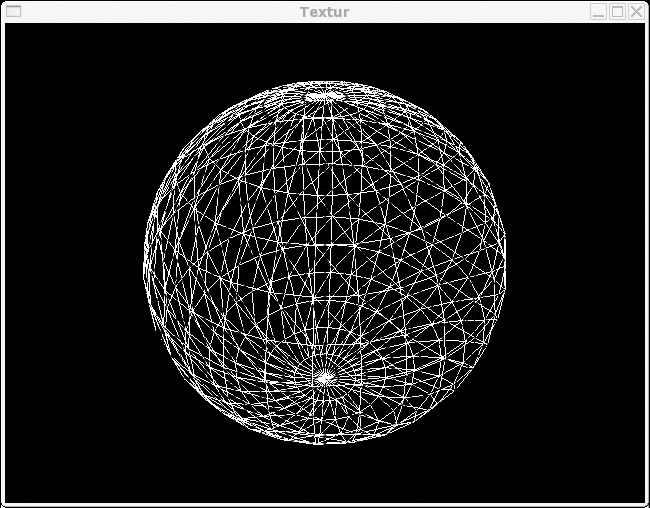
The normal vector is a vector of length 1. It points up vertically from the surface, and thus defines the position of the surface. OpenGL needs this value to calculate lighting and highlights. In our example, the renderSphere function in Line 46 creates a sphere from multiple stripes of triangles (Figure 5a), where the number of stripes is variable. The full version is at the Linux Magazine website; Listing 3 just provides the excerpt with texture processing.
The angle theta2 represents the altitude, and theta3 is the longitude (Lines 49 through 51). First, the script calculates the normal vector. This is totally simple for a sphere. Then glTexCoord2f (Line 55) specifies which point of the texture is applied to which point of the geometry. The sphere requires a projection to paste the flat texture onto the curved surface. The example uses a simple cylindrical projection.
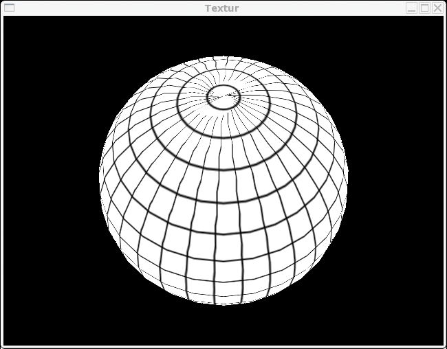
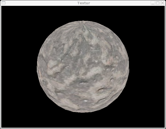
The results are shown in Figure 5c. The square frame from the bitmap (Figure 5d) has been contorted to form triangles at the poles. Finally, glVertex3f specifies the coordinates of a frame point on the sphere to complete the definition of a dot.
The remaining source code then defines triangles for these coordinates and then creates the surface of the sphere. Figure 5a only shows the edges, for demonstration purposes. The texture (Figure 5d) converts this very simple geometry into a fairly realistic image (Figure 5c).
Thus far, we have used the standard lighting with the cold aesthetics of neon light. Just like everything else in OpenGL, however, lighting is a feature you can define down to the last detail. Environmental or spot lights with colors and positions, and the surface material, all influence the color of an object. For materials, you can define both the normal body color, and the color of the highlights.
For example, Listing 4 gives you excerpts from the source code defining a complete image. Users can choose the color of the sphere, the lighting, and the highlights. The script looks familiar with its tclCreateFunc (Line 13), tclReshapeFunc (curtailed), and tclDisplayFunc (Line 37) functions. tclCreateFunc in Line 22 uses glEnable to enable user-definable lighting, and then positions the first light, GL_LIGHT0 (Lines 23 through 25). Then, glEnable enables the material (Lines 28 through 29).
| Listing 4: Light and Color |
01 #!/usr/bin/wish
02 package require tcl3d
03
04 # Startcolorn
05 set ambient  #00d0d0
06 set specular #ffff00
07 set material #eeeeee
08 set emission #000000
09 set shinines 25.0
10
11 # Set position of light
12 # Called once during initialization
13 proc tclCreateFunc {toglwin} {
14   # Background color
15   glClearColor 0.0 0.0 0.0 0.0
16
17   #glPolygonMode GL_FRONT_AND_BACK GL_LINE
18   glShadeModel GL_SMOOTH
19   glEnable GL_DEPTH_TEST
20
21   # Eigenes Licht definieren
22   glEnable GL_LIGHTING
23   glEnable GL_LIGHT0
24   set light_position {1.0 1.0 1.0 0.0}
25   glLightfv GL_LIGHT0 GL_POSITION $light_position
26
27   # Enable material-specific light
28   glColorMaterial GL_FRONT GL_DIFFUSE
29   glEnable GL_COLOR_MATERIAL
30
31   # initialize colors
32   color
33 }
34
35 # Draw new sphere.
36 # Called for each display.
37 proc tclDisplayFunc {toglwin} {
38   # Delete previous geometry
39   glClear [expr {$::GL_COLOR_BUFFER_BIT | $::GL_DEPTH_BUFFER_BIT}]
40   # Create sphere
41   glutSolidSphere 1.0 32 32
42   glFlush
43 }
44
45 # Set material color
46 # Call for each color change,
47 proc color {args} {
48   # Light color
49   glLightfv GL_LIGHT0 GL_AMBIENT  [color2liste $::ambient]
50
51   # Material color for highlights
52   glMaterialf GL_FRONT GL_SHININESS $::shinines
53   glMaterialfv GL_FRONT GL_SPECULAR [color2liste $::specular]
54
55   # Color as light source
56   glMaterialfv GL_FRONT GL_EMISSION [color2liste $::emission]
57
58   # Surface color
59   glColor4fv [color2liste $::material]
60
61   .fr.toglwin postredisplay
62 }
63
64 # Convert HEX color to RGB
65 proc color2liste {color} {
66   set retval {}
67   set liste [winfo rgb . $color]
68   foreach c $liste {
69     lappend retval [expr {$c / 65535.0}]
70   }
71   return $retval
72 }
|
The light and color are defined by the color procedure (Line 47). First, tclCreateFunc calls the color function; the GUI will use this function whenever the colors change. The color procedure sets the color of the light source GL_LIGHT0 using the glLightfv command in Line 49. The color2liste helper (in Line 65) converts the color from the hex representation #fe0000 to RGB 1.0, 0.0, 0.0.
Besides the lighting, the color of the shape plays an important role. The glMaterial group of functions handles this. For our sample sphere, GL_SHININESS and GL_SPECULAR set the color, and intensity of the highlights (Lines 52 through 53). The highlights are those parts of the light that a body reflects directly from a light source back to the viewer. The size and brightness depend on the surface; for example a polished billiard ball has smaller and brighter highlights than a rough wooden sphere.
Most bodies do not emit light themselves, but you can use OpenGL to depict light bulbs and neon lights. Color GL_EMISSION (Line 65) lets you do this, by specifying the light emitted by the body. Finally, glColor4fv (Line 59) defines a color, which applies to the next defined geometry.
tclDisplayFunc creates a new sphere whenever it is called. To do so, it draws on a GLUT (GL Utilities) library function: glutSolidSphere (Line 41) creates a sphere of triangles with the specified radius and resolution. As this will always follow the color procedure, it adopts the material and surface color defined there. The remaining window dressing is comprised of normal Tk with buttons to change the colors.
The methods we have discussed thus far use a script to create, move, and light geometries, and cover them with textures. However, the procedure for moving an image of a whole vehicle or a house can be fairly complex . Tools such as Ayam [15], or Blender [11] facilitate the process. They provide a CAD system specially for surface models, and even support modifying and tailoring of textures.
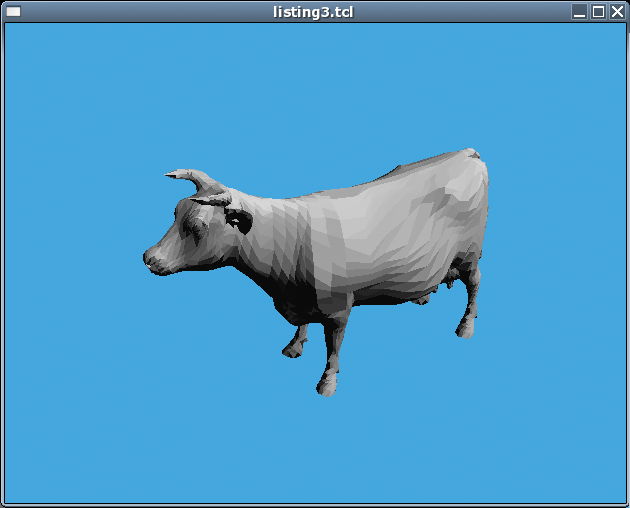
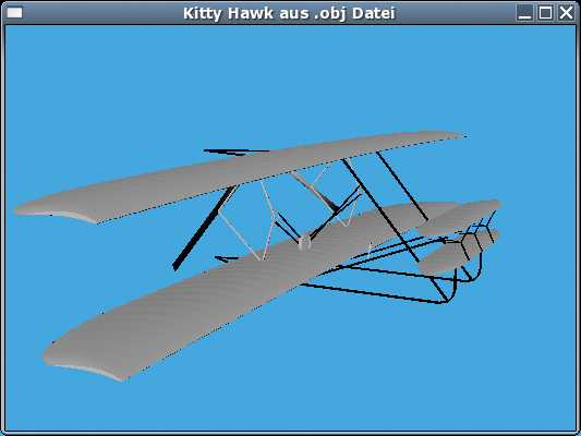
Thanks to Nate Robins GLM library, OpenGL scripts can import finished models, if they are provided in Object Wavefront format (.obj). This library is part of the Tcl3D package, although it is available for other programming languages. The Wright Brothers' legendary Kitty Hawk plane serves as an example in Figure 6. The VRML model from [16] can be converted into an .obj file using Blender [11] (a download is available from [3]). Listing 5 reads the obj file and puts the model on your screen.
| Listing 5: Loading a Wavefront Model |
01 # Set start values and generate display list.
02 # Called when creating the window.
03 proc tclCreateFunc {toglwin} {
04     # Black background
05     glClearColor 0.1 0.7 1 0.5
06
07     # Some tuning
08     glClearDepth 1.0
09     glEnable GL_DEPTH_TEST
10     glShadeModel GL_SMOOTH
11     glDepthFunc GL_LEQUAL
12     glHint GL_PERSPECTIVE_CORRECTION_HINT GL_NICEST
13
14     glEnable GL_DEPTH_TEST
15     glEnable GL_LIGHTING
16     glEnable GL_LIGHT0
17
18     # Read file
19     set filename "untitled.obj"
20     set ::objId [glmReadOBJ $fileName]
21     glmFacetNormals $::objId
22     glmVertexNormals $::objId 90.0
23 }
24
25 # Display 3D model
26 proc tclDisplayFunc { toglwin } {
27     # Delete screen and depth buffer
28     glClear [expr $::GL_COLOR_BUFFER_BIT | $::GL_DEPTH_BUFFER_BIT]
29
30     # Set starting position
31     glLoadIdentity
32     glTranslatef $::Posx $::Posy $::Posz
33     glRotatef $::Rotx 1.0 0.0 0.0
34     glRotatef $::Roty 0.0 1.0 0.0
35     glRotatef $::Rotz 0.0 0.0 1.0
36
37     glmDraw $::objId [expr $::GLM_SMOOTH | $::GLM_MATERIAL]
38     $toglwin swapbuffers
39 }
|
On initializing, tclCreateFunc (in Line 3) loads the model, drawing on the glmReadObj function in Line 20. glmFacetNormals and glmVertexNormals (Lines 21 and 22) calculate the normal vectors required by OpenGL. The model is then ready for displaying; In Line 26, tclDisplayFunc draws the model by calling glmDraw in Line 37, using the SMOOTH and MATERIAL flags. All done! Instead of individually defining thousands of triangles, the script has loaded a complete model in just a few steps.
| INFO |
|
[1] OpenGL: http://www.opengl.org
[2] Tcl3D: http://www.tcl3d.org [3] Togl: http://togl.sourceforge.net [4] SDL: http://www.libsdl.org [5] Mesa: http://www.mesa3d.org [6] Mason Woo, Jackie Neider und Tom Davis, "OpenGL Programming Guide" (Redbook): Addison-Wesley [7] Dave Shreiner, "OpenGL Reference Manual" (Bluebook): Addison-Wesley sowie http://www.rush3d.com/reference/opengl-bluebook-1.0 [8] Nehe: http://nehe.gamedev.net [9] Open Cascade: http://www.opencascade.org [10] Tclgl2ps: http://www.sfu.ca/~gay/tclgl2ps.zip [11] Blender: http://www.blender.org [12] Downloads for this article: http://ftp.linux-magazin.de/pub/listings/magazin/2006/07/3D-Skripting [13] Free textures from Mayang: http://www.mayang.com/textures/ [14] Woodgrains: http://www.woodworking.org/WC/woodsampler.html [15] Ayam: http://ayam.sourceforge.net [16] 3D model of the Kitty Hawk: http://www.ocnus.com/models/Vehicles/ |