
By Ludger Köhler, Charly Kühnast, Mark Schier, and Werner Thal
Managing a big enterprise network takes a sound basis of theoretical knowledge and a great deal of experience. Linux Magazine asked author and sysadmin guru Charly Kühnast for a couple of hands-on reports based on his daily experiences. At first, Charly mumbled something about being overworked and bolted down the hallway. But just two doors down, he stopped and talked his co-workers into helping him out with anecdotes from their daily life. And as the guys run a fairly impressive network, they have plenty of tales.
Network fun starts at the lowest layers: the number of wires between a computer and the next switch does not necessarily have to be one. And sometimes it takes weeks of painful trial and error to find out if a switch or a router is the best solution. Even the tried-and-trusted DHCP protocol has a bunch of surprises up its sleeves.
A single Ethernet interface is not enough in some cases. You may need failover mechanisms, or a single NIC may not have the kind of throughput you are looking for (Figure 1). In this case, it makes sense to group multiple cards to form a bonding interface. The reference documentation for this is the bonding.txt Howto for your kernel. Check out your Linux sources, such as /usr/src/linux-2.6.5-7.257/Documentation/networking/bonding.txt.

After configuring a virtual master interface (starting at bond0) and mapping physical interfaces (such as eth0 and eth1) to the master interface, you need to launch the bonding module with the required parameters. Mode 0 or 2 handles load balancing, and mode 1 provides an active backup. Mode 0 uses a round-robin approach to load balancing, whereas mode 2 uses an XOR algorithm.
From a networking point of view, mode 2 is definitely preferable. Although mode 0 distributes packets evenly across all links, there is a danger of packets from a single session overtaking each other on different links. This would be fatal for some UDP applications, and in a worst-case scenario, even TCP might be unable to reconstruct the original sequence, which could cause the session to fail. Cisco switches do not even support round robin.
The XOR variant is more intelligent. XOR creates a way for the source and target MACs to decide which of the available links to use for a connection. As long as the source and target MACs stay the same, the routing decision will not change, and this means that all the packets in a session will use the same path.
When more than two interfaces exist, it is important for the bonding system to know which physical interface maps to which ethx. As the kernel itself decides how to assign these numbers, ethtool with the -p parameter can help you. Entering the command causes the link diode on the interface to flash rhythmically (see [1]).
This is really useful if you retrofit a NIC (Figure 3). Often, the operating system will juggle the physical/ethx mappings. You end up with completely different interfaces in a bond. If you can't find out which ethx maps to which port, it's more trial and error.

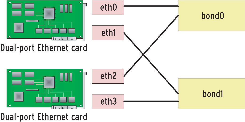
If you are setting up two or more bondings via dual-port interface cards (with two ports per card), it is important to bond interfaces on different cards (Figure 2). This is the only way to ensure that you will have one link per bond if a NIC fails. If you require redundancy but not load balancing, it might make more sense to distribute the links over different Ethernet switches (Figure 1). This would mitigate the impact of switch failure on operations.
If the double connection to the switch is not intended for active backup mode (that is, as a failover mechanism), you may be intending it for load balancing, that is, the task of distributing the load evenly over the two paths. You need a way of telling the Ethernet switch what you are attempting to do, and this is what configuring an Etherchannel does for you. If you have a Cisco switch, the command for this is channel mode on. This tells the switch to set up a channel and not to use automatic detection methods to check the status on the other end of the connection. If you forget this, you'll have to do more troubleshooting.
The iptraf [2] command line tool can quickly give you a good idea of how the load is distributed over the bond interfaces. But Cacti [3] is much better for long-term statistics.
The idea behind virtual LANs is actually fairly simple: VLANs connect physically separate Ethernet segments. On a switch, every port represents a separate segment. Instead of allowing every segment to talk to every other segment, a VLAN assigns segments to static groups. Unfortunately, Cisco causes some confusion here by using some terms differently from the rest of the world.
In Cisco-speak, a trunk is what other vendors call tagging or 802.1q (Dot1q). To add more confusion, Cisco's channels or Etherchannels are called to trunks by others. Linux decided that attack was the best form of defense and introduced a previously unused term, bonding.
Some Cisco quirks are also noticeable in the spanning tree protocol. The box titled "Spamming Tree Protocol" gives you a short overview of vendor-independent STP events. Cisco has been the only vendor thus far to decide that STP scales well and provides high levels of operational safety in complex structures. If you need strong backbone performance, there is no avoiding switching and STP.
Cisco network design is based on a three-layer model that divides networks into the core, distribution, and access layers (Figure 4). Fast switches designed to move packets from A to B as quickly as possible within a VLAN form the core. The distribution layer ensures correct distribution of packets across VLAN orders, relying on traditional routing to do so. The access layer contains terminal devices, that is, workstations, servers, printers, and more.

| Spanning Tree Protocol |
|
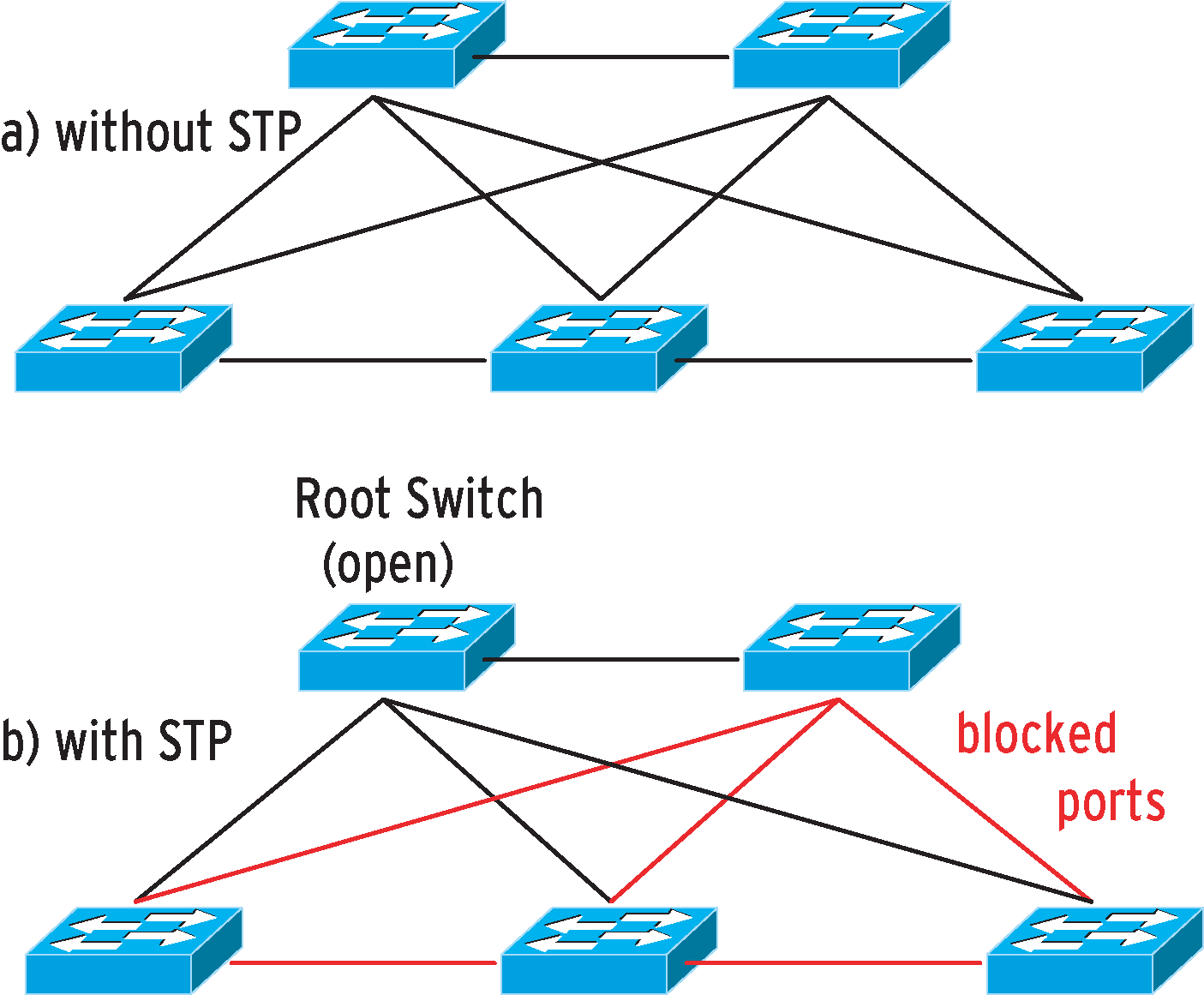
Many cooks spoil the broth, and many switches spoil the network despite the admin's best intent. The aim is typically to improve network resilience, but ham-fisted patching can quickly create a virtual particle accelerator. A loop is characterized by the fact that it will keep packets traveling in infinite circles. If the network has two or more redundant paths, and the nodes send frames to multiple interfaces, the result could be a loop, in which packets keep traveling in infinite circles. As Ethernet frames do not support hop counts or time-to-live values, the network would not notice this infinite Odyssey, leaving the packets circulating for ever. To avoid this disaster, clever people designed the Spanning Tree Protocol (STP) [4], where all the switches on a network negotiate a root bridge. The algorithm immediately grants all connections that link directly to the root bridge (Figure 5), or at least know a better path to the root bridge than the rest of the network. The remaining, redundant paths with less effective connections are then blocked for network traffic. To elect the root bridge, the switches exchange BPDUs (Bridge Protocol Data Units). This process typically takes up to 30 seconds to complete, although it can take longer, and it restarts whenever a redundant connection fails, or when a new switch or a redundant path are added. The aim is not to discover the optimum path from a source to every target (you need a routing protocol to do this) but simply to ensure a loop-free network. If an Ethernet frame is unlucky because STP has blocked the shortest path for it, it has to detour. On the upside, it will always reach the target, and duplicates cannot occur. |
As high-performance routing hardware was simply not available (or affordable) for a long while, good backbone performance was always the main argument for powerful switches in the core layer. This is how the authors of this article set up their own network and many customer networks. It was an approach that worked well, except in situations in which itinerant users plugged cables into office switches. In those situations, we had a lot of fun troubleshooting - as you are probably aware, switching and STP tend to throw errors at a completely different part of the network than that of the error source.
The going started to get really tough when we needed to extend the network, adding ports, and providing enhanced redundancy at the same time. What actually happened was that we achieved the opposite effect; whenever we added a switch with a redundant link, this caused a total failure of the core and distribution areas.
As this happened on a number of occasions, Werner Thal was nicknamed the "Master of Loops." As a workaround, he disabled the redundant paths, but obviously things couldn't stay that way as there was a good reason for wanting redundancy - to provide a fallback network in case of failure.
Theoretically, redundancies should not have any effect on the network, and they most definitely shouldn't slow it down to a snail's pace. An external consultant also failed to find the cause of the failure at first.
As Cisco uses PVST (Per-VLAN Spanning Tree) on its components, the consultant first reduced the overhead by only permitting the VLANs really needed for each trunk connection. He also replaced STP with RSTP (Rapid Spanning Tree Protocol), a successor that promises faster convergence.
Although these steps definitely improved things, ultimately it was a Cisco switching course that provided the vital clues. In contrast to the vendor's promises, STP does not actually scale well in a production environment.
When you get down to the nitty gritty, the reason for this fatal STP behavior is the fact that BPDUs are generated by the software on the switch. If a switch that has a lot more to do than to just send BPDUs is suddenly hit by heavy traffic, a CPU bottleneck can occur. The switch does not have enough CPU capacity to generate BPDUs, and it is thus unable to send these packets.
Unfortunately, neighboring switches interpret missing BPDUs as a switch failure and enable disabled ports to compensate for the failure. This introduces loops that cause a dramatic increase in network load, which in turn takes up so much of the switches' time that even more components fail to produce BPDUs. The vicious circle just keeps on going until the whole network disappears into a black hole.
The switching course trainer gave us some surprising advice: Do without switching as much as possible, focus on routing, and restrict the number of layer 2 instances to a maximum of three devices per VLAN. Although this strategy might be difficult to implement precisely in a production environment, we soon discovered that micro-segmenting at the IP level worked miracles.
Routing-induced performance problems are now mostly a thing of the past, as current hardware can easily cope with the network bandwidth (wirespeed routing). The marketing blurb for this is layer 3 switching.
The fact is that this is hardware-based routing with some optimization thanks to mechanisms such as CEF (Cisco Express Forwarding). At the end of the day, you have a nicely scaled, and stable, routed LAN that uses an appropriate routing protocol, such as OSPF (Open Shortest Path First).
Virtualization technologies such as VMware [5] are really practical if you need to test new software or services without deploying new hardware. On the downside, they give unsuspecting admins any number of opportunities to shoot themselves in the foot.
On Linux, the VMware installation is semi-automated and relies on the vmware-install.pl script. After checking a couple of dependencies, (such as GCC and kernel headers), the script will prompt you for a couple of paths, and, typically, you can then just accept the defaults shown.
If you need to test server-based services, it makes sense to configure a loopback interface for the VMware guest, or at least a private subnet that your LAN environment will not be able to see. However, you can't expect everybody to be this cautious when trying out virtualization, and VMware has an unfortunate tendency to try to share your existing network: Configure a bridged network for vmnet0 is the default option. Now, just imagine the fun you can have in the networking department if you happen to run a DHCP daemon on one of your virtual servers.
Of course, a DHCP server running under VMware will respond to DHCP requests off the LAN, and often far more quickly than the enterprise DHCPD. The official server will typically have other services to provide, such as DNS, and thus have a much greater load than the VMware-based server, which will twiddle its thumbs for most of the day and jump to respond to the few requests that eventually come its way.
As DHCP does not have a mechanism for distinguishing between rogue and legitimate DHCP sources, this fairly inconspicuous service can cause turmoil on the network. To root out the miscreant, the administrator needs its address. There are two ways of discovering the address: First of all, you could sacrifice your laptop and allow the VMware DHCPD to assign an address to it. The ARP table on your laptop will tell you the DHCP server's MAC address. The second approach is to run one of the dhcping tools [6] on your normal desktop to discover the MAC address.
After discovering the enemy's MAC address, it's time for some detective work on the access switches where the CAM (Content-Addressable Memory) tells you the MAC addresses for each port. Then, in inimitable administrator-from-hell style, just disable the port, leave your office, and hang around in the corridor until you hear somebody shouting "Hey, my Vmware is down!".
Networks of all sizes can hold any number of surprises for their unsuspecting admins. If you run up against a major problem, the best thing you can possibly do is to seek help from other experienced professionals.
Viewed in this light, it was a good thing that Charly turned to his co-workers for some assistance. This reveals our all-star admin as a professional through and through.
| INFO |
|
[1] Gkernel (contains Ethtool): http://sourceforge.net/projects/gkernel
[2] IPtraf: http://iptraf.seul.org [3] Cacti, the web front-end for RRD-Tool: http://www.cacti.net [4] Cisco documentation, "Understanding Spanning-Tree Protocol": http://www.cisco.com/univercd/cc/td/doc/product/rtrmgmt/sw_ntman/cwsimain/cwsi2/cwsiug2/vlan2/stpapp.htm [5] VMware: http://www.vmware.com [6] dhcping implementation: http://www.mavetju.org/unix/general.php and http://dhcping.openwall.net |