
By TOMASZ BARTCZAK, MACIEJ PIECHOWIAK, TOMASZ SZEWCZYK, and PIOTR ZWIERZYKOWSKI
IP networks have supported multicast transmission for nearly 20 years, but the technology has only recently entered the realm of widespread use. As the name implies, multicasting is a technique for transmitting data from a single source to a predefined collection of recipients. This concept poses some special challenges that aren't seen in more conventional transmission techniques, such as broadcasting, in which the message is sent to all computers on a network segment, and unicasting, in which a message passes from a single source to a single recipient.
Efficient use of multicasting can significantly reduce traffic load, especially on networks that support streaming-style multimedia transmissions. Multicasting applications and technologies have received increased attention with the rise of audiovisual technologies; however, multicasting remains a mystery to many software developers, system admins, and end users who might benefit from more extensive use of this promising technique. In this article, we offer a glimpse at the practical side of multicasting, including a sample configuration that uses the free XORP routing protocol suite.
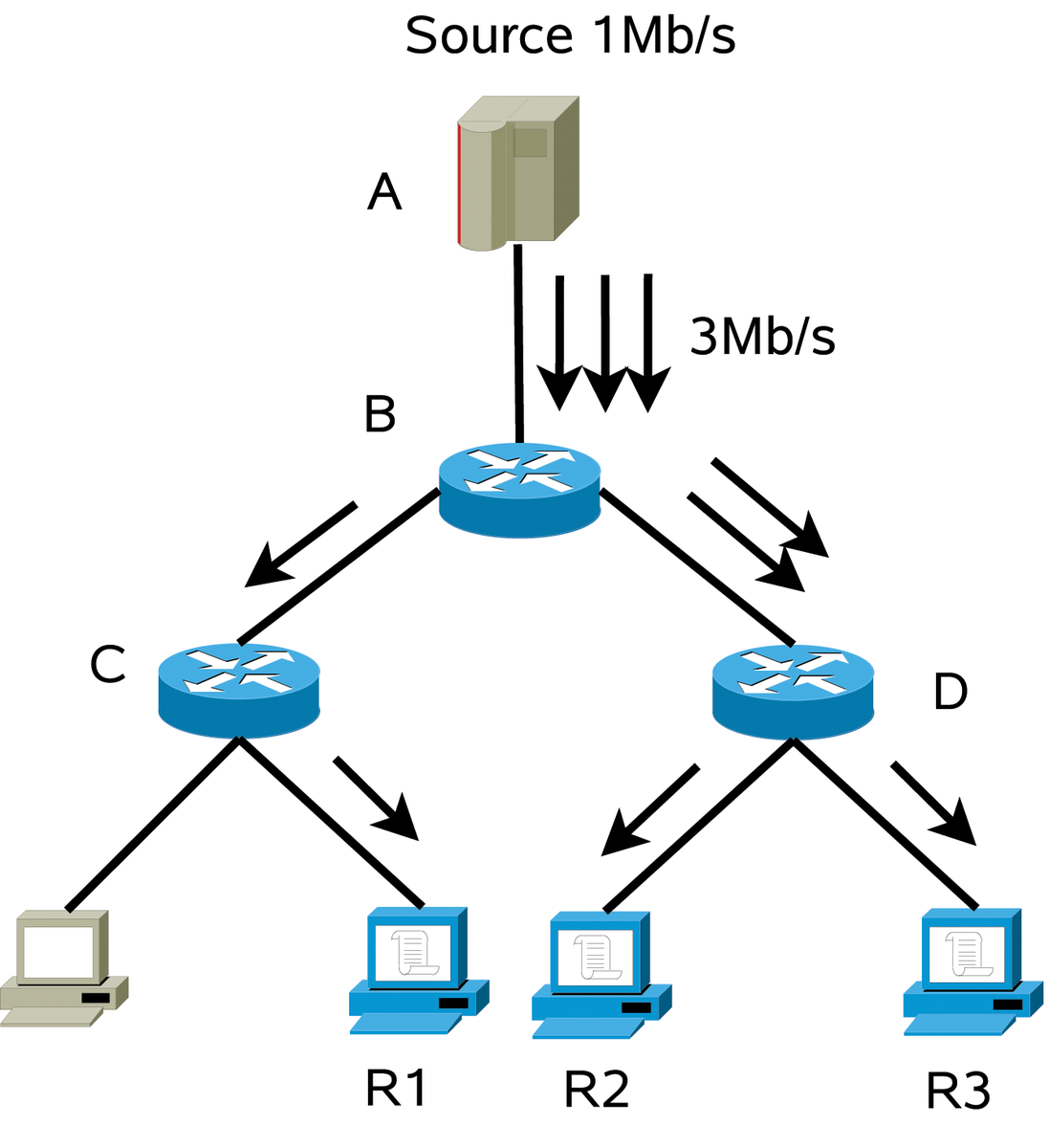
Figure 1 shows the idea behind multicast transmission. Source A generates a data stream with throughput of 1Mbps, and the data stream is received by three recipients. Figure 1a shows a unicast transmission between the source and the receivers. The transmission results in three independent, but identical, data streams, which means that a bandwidth of 3Mbps is consumed on the link between the source and distribution networks. In contrast, a multicast scenario (see Figure 1b) requires only one data stream from the source, so the load on the link is constant and independent of the number of receivers.

Transmission at the Data Link Layer is performed through the use of the MAC address, which identifies a network interface on the link. MAC addresses are mapped to and from the corresponding IP addresses with the help of the address resolution protocol (ARP) and reverse ARP (RARP). For example, if router B wants to send data to router D, it first sends an ARP request to D's IP address. In response, D sends an ARP reply that contains its MAC address. Once this process is finished, B and D can communicate over the Ethernet transmission medium. In the case of multicasting, the question is how to achieve the effect of Data Link addressing without incurring the overhead of having to resolve an IP address to an arbitrarily complex tangle of recipient MAC addresses.
This particular problem is solved by mapping an IP multicast address to a single MAC address that is then used by all recipients. An ethernet MAC address consists of 48 bits. Ethernet addresses that start with the bit sequence 01.00.5E are assigned to IANA (Internet Assigned Number Authority, the organization responsible for managing IP address ranges). IANA has decided to allocate half of the assigned Ethernet address range to the purpose of multicast transmission. As a result, 23 bits of the MAC address are available for the purpose of group communications.
An IP address, however, has 32 bits, which means 32 bits of the IP address must map to 23 bits of the MAC address. All IP addresses from Class D are reserved for multicast transmission purposes. IP addresses belonging to Class D start with the bit pattern 1110. Because this pattern is constant for all multicast addresses, it doesn't have to be part of the mapping. Consequently, only 28 bits of the IP address are mapped to 23 bits of the MAC address representation. Figure 2 shows how the mapping procedure works.
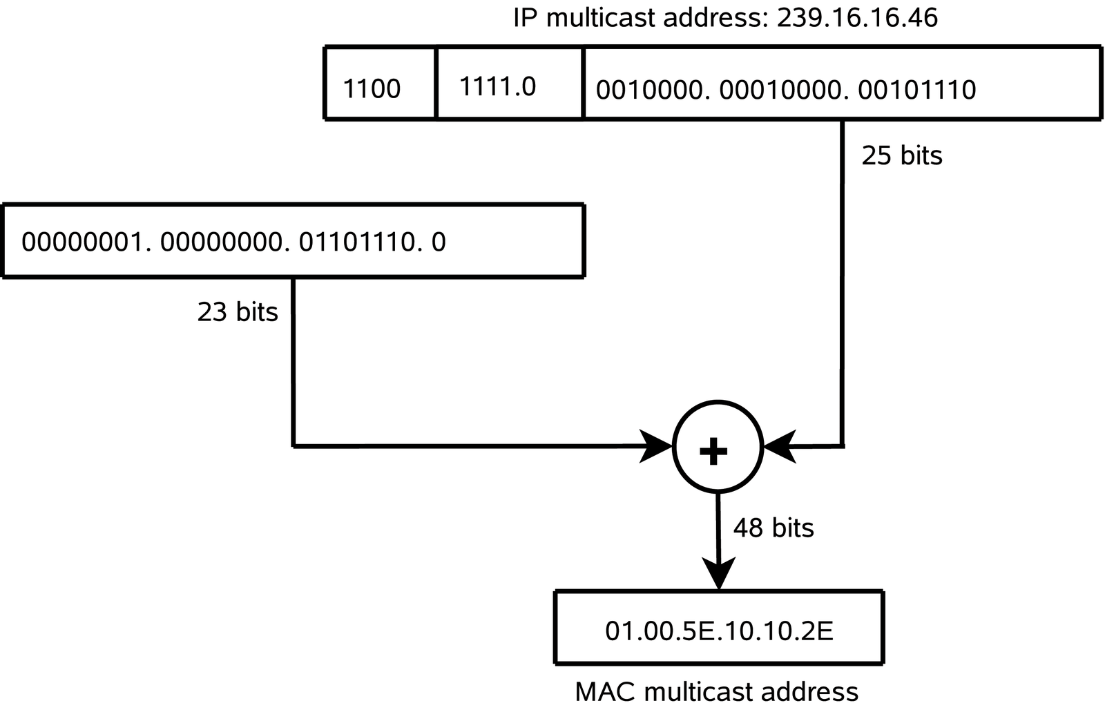
As you can see in Figure 2, after discarding the initial 4 bits, the next 5 most-significant bits are also ignored. The remaining 23 bits are then directly mapped to the MAC address. Note that this mapping of IP to MAC multicast addresses is not unambiguous; the relation between IP and MAC addresses is not one-to-one. Consequently, 25 IP group addresses have the same MAC addresses.
A simple example will illustrate this process. Consider the multicast address 239.16.16.46, which has the following binary representation: 11101111.00010000.00010000.00101110.
Discard the 4 most-significant bits (the Class D bit pattern) and you have the following sequence: 1111.00010000.00010000.00101110.
If you omit the next 5 bits, for 0010000.00010000.00101110, and combine this bit pattern with the sequence assigned by IANA for the purpose of multicast transmissions, you can compute the MAC address 01.00.5E.10.10.2E corresponding to the IP address 239.16.16.46.
| Building a Tree |
|
To receive multicast transmissions, receivers send a data reception demand to the router. This demand is transmitted with IGMP (Internet Group Management Protocol) or, to be more precise, with the help of the IGMP Report message. The router, after receiving the message, sends a Join packet of the PIM-SM protocol to other routers along the path. The routers are thus responsible for the construction of a multicast transmission tree for the transmission of group data between the receivers and the source. In theory, you do not even need a dynamic multicast routing protocol to build this transmission tree. The smcroute program (the equivalent of the route application for unicast transmission) lets you manually configure multicast routes. As in the case of the unicast transmission, manual configuration often leads to errors and is additionally troublesome when the network configuration is changed. Moreover, multicast transmission trees are usually constructed for a relatively short period of time (for instance, a two-hour movie transmission). This, in practice, excludes the possibility of manually creating the multicast transmission tree in a real-world situation. The only real possibility of implementing group transmission at a practical level is through a multicast routing protocol. |
When an application requests reception of multicast transmission, the kernel network subsystem computes the corresponding MAC address. This address is then added to the list of received multicast addresses; finally, the kernel calls set_multicast_list from the net_device structure. The set_multicast_list function performs some hardware-specific actions at the driver level so the network card will be able to receive packages sent to this specific MAC address.
Figure 3 shows an example of a multicast transmission taking place between two systems connected to the same Ethernet network segment. The application on computer A transmits data to multicast address 239.16.16.46 (step 1a in Figure 3). The application passes the data, together with the destination address, to the kernel. The kernel then computes a MAC address corresponding to this IP address.
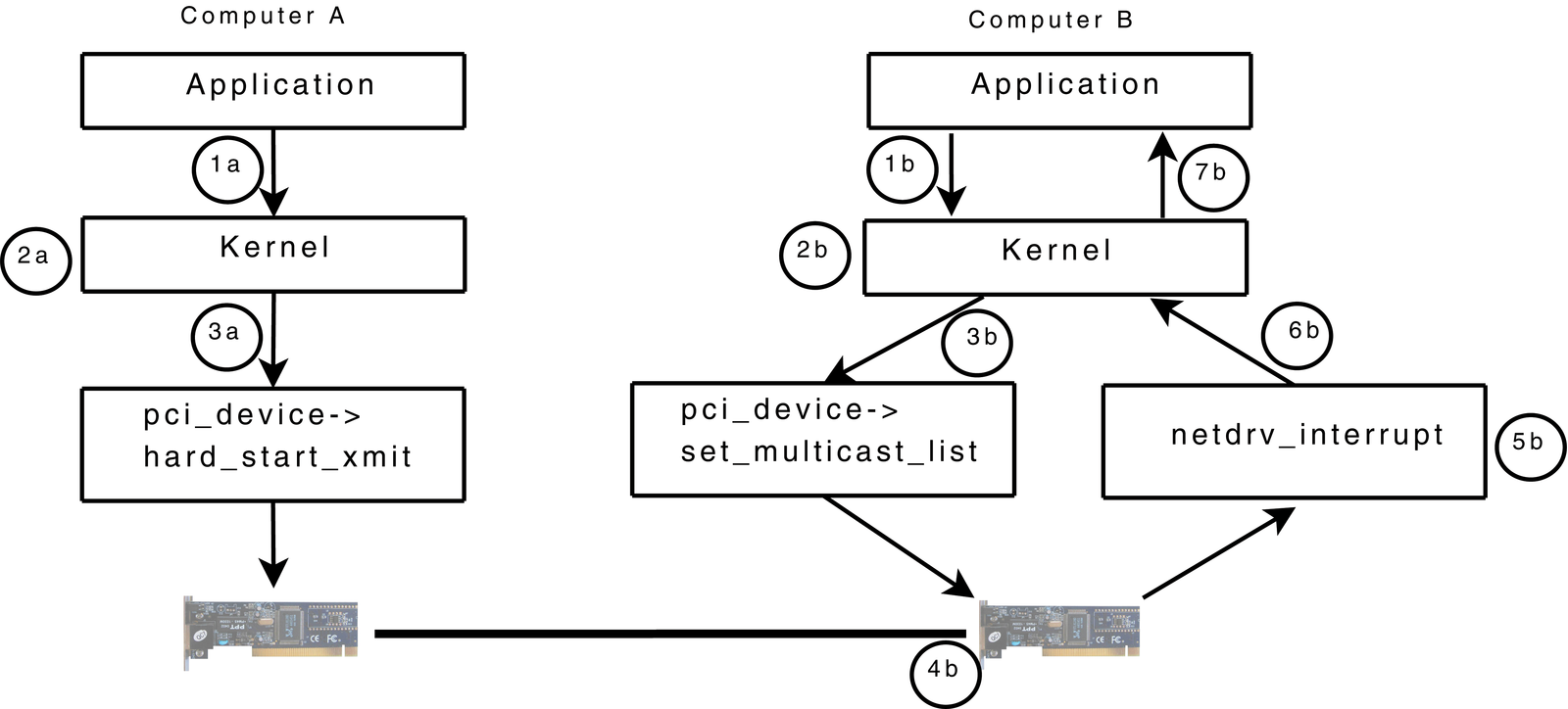
On the other end, the application on computer B informs the Linux kernel that it is interested in receiving a multicast transmission sent to IP address 239.16.16.46 (step 1b in Figure 3). The kernel computes the MAC address corresponding to this IP address (2b) and informs the network card that it should receive packages sent to this MAC address (3b). Once the data package is received (4b), the network card installed in computer B generates an interrupt, and the method responsible for interrupt handling is called (5b). This method hands over the received data to the kernel (6b), which will ultimately relay that data to the application (7b).
Multicasting is so efficient that you might wonder why everyone isn't already using it. The problem is the need to include additional functionality in the transmission network that guarantees appropriate service and replication of the single data stream over a large routed network. Passing the data efficiently through a chain of routers requires a new class of special-purpose multicast routing protocols. Unfortunately, these protocols are rather complex and thus are not commonly implemented by Internet providers.
A multicast routing protocol must support the possibility of forwarding a single packet to multiple interfaces. Currently, the most popular multicast routing protocol is PIM-SM (Protocol-Independent Multicast--Sparse Mode). The principal task of the PIM-SM protocol is to build a multicast distribution tree that delivers multicast packets from the source to the receivers. For multicast transmission, PIM-SM maintains a separate routing table called the Multicast Forwarding Cache (MFC).
PIM-SM also uses a unicast routing table to provide a loop-free forwarding environment for multicast deliveries. Therefore, to guarantee the appropriate functioning of the PIM-SM protocol, it is also necessary to configure the unicast routing tables on the computers that are involved in the multicast transmission.
The PIM-SM protocol uses the concept of a rendezvous point to manage multicast communication. The rendezvous point is a router that will receive transmission requests from recipients. Transmission sources send their data to the rendezvous point. PIM-SM can assign the rendezvous point role dynamically, or the user can assign the role directly through the configuration.
XORP is a free routing suite that includes the exceptionally good implementation of the PIM-SM protocol [1]. A quick look at mulitcast routing with XORP should give you a good idea of how to get started with your own mulitcasting experiments.
First, download the source code from the project website [2] (in this article, we use version 1.5 of July 22, 2008) and install it as follows:
tar xzf xorp-1.5.tar.gz
./configure
make
make check
make install
In this discussion, we assume the modules servicing network cards have already been loaded or complied into the kernel and that the network has not been configured in any way. (Before you start the configuration, configuration tools such as NetworkManager should be switched off.)
The first step is to run the program that configures the XORP application with the command xorpsh (the executable files of the XORP application are in /usr/local/xorp/bin). Because XORP significantly affects the functioning of the system, it has two modes of operation: basic and enhanced. Working in the enhanced mode requires that anyone starting the program must belong to the xorp group.
Configuring the network and the PIM-SM protocol requires the following steps:
The XORP management interface is similar to the devices made by Juniper. Listing 1 shows the configuration of the network interfaces.
The first command in Listing 1 results in entering enhanced mode, in which a change in the configuration of the device is possible. The next two set interfaces commands are responsible for the configuration of the network interfaces. As you can see, the syntax of the command is very simple and does not require explanation. In the next steps, the interfaces are activated. The last command is commit, which allows the execution of the preceding commands.
| Listing 1: Configuring the Network Interfaces |
01 >configure 02 # set interfaces interface eth0 vif eth0 address 192.168.2.1 prefix-length 24 03 # set interfaces interface eth1 vif eth1 address 192.168.3.2 prefix-length 24 04 # set interfaces interface eth0 vif eth0 disable false 05 # set interfaces interface eth1 vif eth1 disable false 06 # commit |
As stated earlier, the PIM-SM protocol uses a unicast routing table to know where to send the Join messages. Routing tables on individual routers can be configured manually with the route or ip commands. This approach, however, is troublesome and prone to error, requiring an intervention of the operator every time the configuration is to be changed.
Dynamic routing protocols allow automatic determination of routing tables. A common dynamic protocol supported by XORP is OSPF (Open Shortest Path First). A full discussion of unicast routing protocols exceeds the scope of this article; however, the configuration steps in Listing 2 show how to configure unicast routing with OSPF.
Also, you must enable unicast data forwarding with:
# set fea unicast-forwarding4
# commit
| Listing 2: Configuring OSPF |
01 # set protocols ospf4 router-id 192.168.2.1 02 # set protocols ospf4 area 192.168.0.0 interface eth0 vif eth0 address 192.168.2.1 03 # set protocols ospf4 area 192.168.0.0 interface eth0 vif eth0 disable false 04 # set protocols ospf4 area 192.168.0.0 interface eth1 vif eth1 address 192.168.3.2 05 # set protocols ospf4 area 192.168.0.0 interface eth1 vif eth1 disable false 06 # commit |
Listing 3 shows the steps for enabling multicast transmissions. As you can see, multicasting is enabled for individual interfaces and for the unicast interface.
| Listing 3: Enabling Multicast Transmission |
01 # set plumbing mfea4 disable false 02 # set plumbing mfea4 interface eth0 vif eth0 disable fasle 03 # set plumbing mfea4 interface eth1 vif eth1 disable fasle 04 # set plumbing mfea4 interface register_vif vif register_vif disable fasle 05 # commit |
The final step in the configuration is to enable the PIM-SM protocol. Start by loading the daemon of the PIM protocol:
# set protocols pimsm4 disable false
# commit
The #commit command will be executed with a slight delay because of the initiation of the process responsible for the service of the multicast routing protocol. Subsequent commands, presented in Listing 4, configure the PIM-SM protocol.
The commands in Listing 4 activate the PIM-SM protocol service on individual interfaces, as well as on the virtual interface register_vif, which is used to transfer data over a unicast tunnel from the source to the rendezvous point. Additionally, the address of the rendezvous point, which is 192.168.3.1 in this case, is allocated. The group-prefix setting denotes the range of multicast addresses serviced by a given rendezvous point.
| Listing 4: Configuring PIM-SM |
01 # set protocols pimsm4 interface eth0 vif eth0 disable false 02 # set protocols pimsm4 interface eth1 vif eth1 disable false 03 # set protocols pimsm4 interface register_vif vif register_vif disable false 04 # set protocols pimsm4 static-rps rp 192.168.3.1 group-prefix 224.0.0.0/4 05 # commit |
The configuration presented so far makes it possible to transfer data from the source to particular receivers. The receivers, however, must be able to inform routers that they are interested in receiving multicast transmissions. As we described earlier, this information passes through the network via IGMP, so you must configure IGMP on the routers that have local receivers.
At this point, you might be wondering why it is necessary to configure IGMP through XORP when the kernel already supports IGMP.
The problem is that the implementation of IGMP that is included in the kernel does not provide the server side of IGMP, which means that the built-in kernel implementation will not forward information in IGMP messages to the multicast routing protocol.
As in the case of PIM-SM or OSPF, the IGMP configuration requires activation of a daemon responsible for the service of the protocol:
# set protocols igmp disable false
# commit
In addition, you must indicate the interfaces serviced by IGMP:
# set protocols igmp interface eth2 vif eth2 disable false
# commit
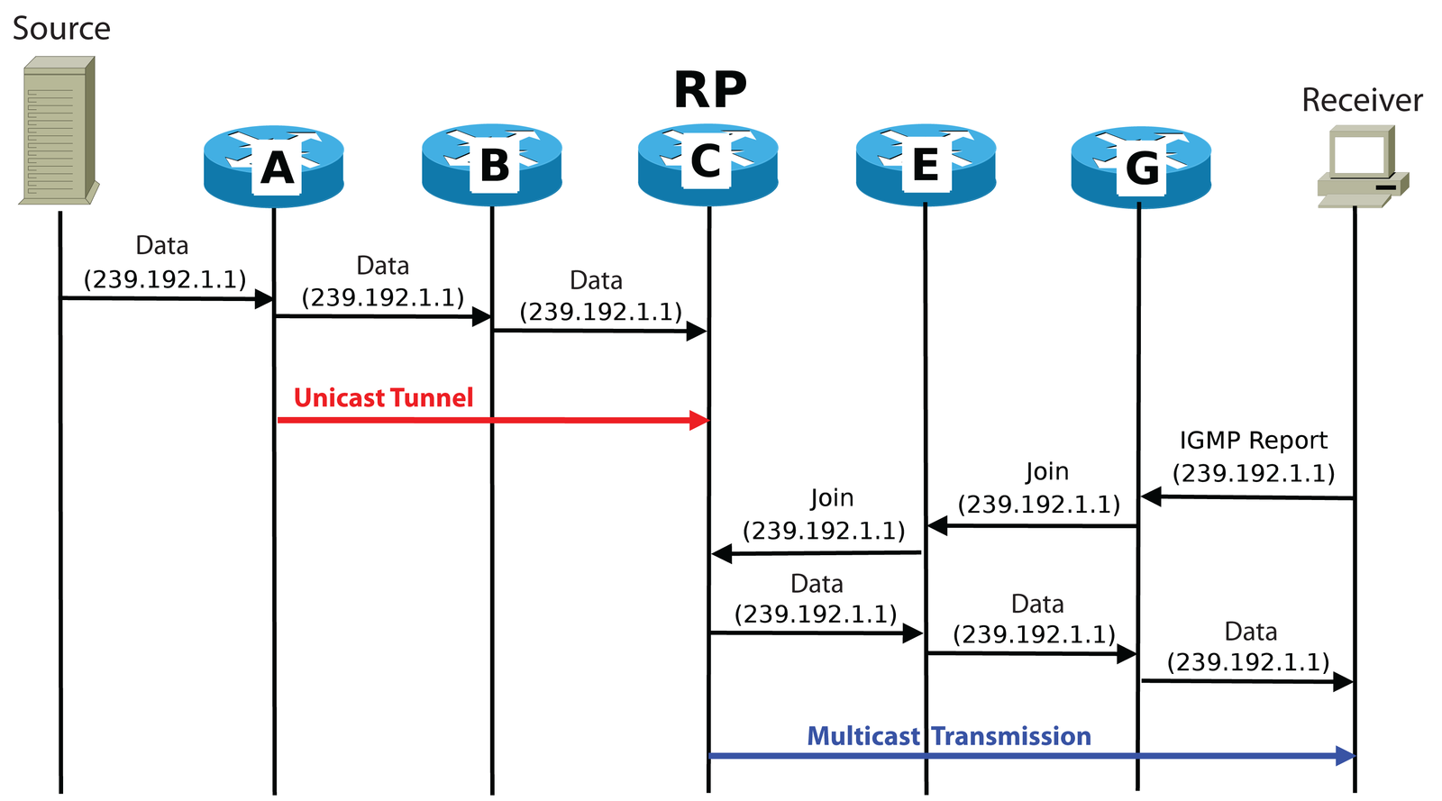
Figure 4 shows the whole transaction at a glance. As you can see, the computer on the left starts by sending a video sequence to the address 239.192.1.1. Router A, directly connected to the source, starts sending data to the rendezvous point through a unicast tunnel. The application on the receiving end generates an IGMP Report message. This message is processed by the router, which is followed by a Join message of the PIM-SM protocol sent toward Router C, which is acting as the rendezvous point RP. On receiving the message, Router C sends the multicast transmission in the direction of this receiver, plus any other receivers in the group that will receive the multicast data.
Multicasting is a complex issue, and here we present only the most basic concepts. Nevertheless, this brief introduction should give you a head start in determining how best to implement multicasting in your own environment.
| INFO |
|
[1] XORP: http://www.xorp.org/
[2] XORP download: http://www.xorp.org/downloads.html |
| THE AUTHOR |
|
Over the last few years, the authors, Tomasz Bartczak, Maciej Piechowiak, Tomasz Szewczyk , and Piotr Zwierzykowski have worked with network technologies and Unix/Linux operating systems. Additionally, they are interested in research activities focusing on multicast algorithms and protocol optimization. |