By the Blendax project
In the gaming industry, many programmers work on creating graphics that provide a realistic impression of water. While developing the award-winning BioShock game, for instance, 2K Games even went so far as to employ programmers who specialize in fluids to give the underwater city Rapture a more life-like appearance.
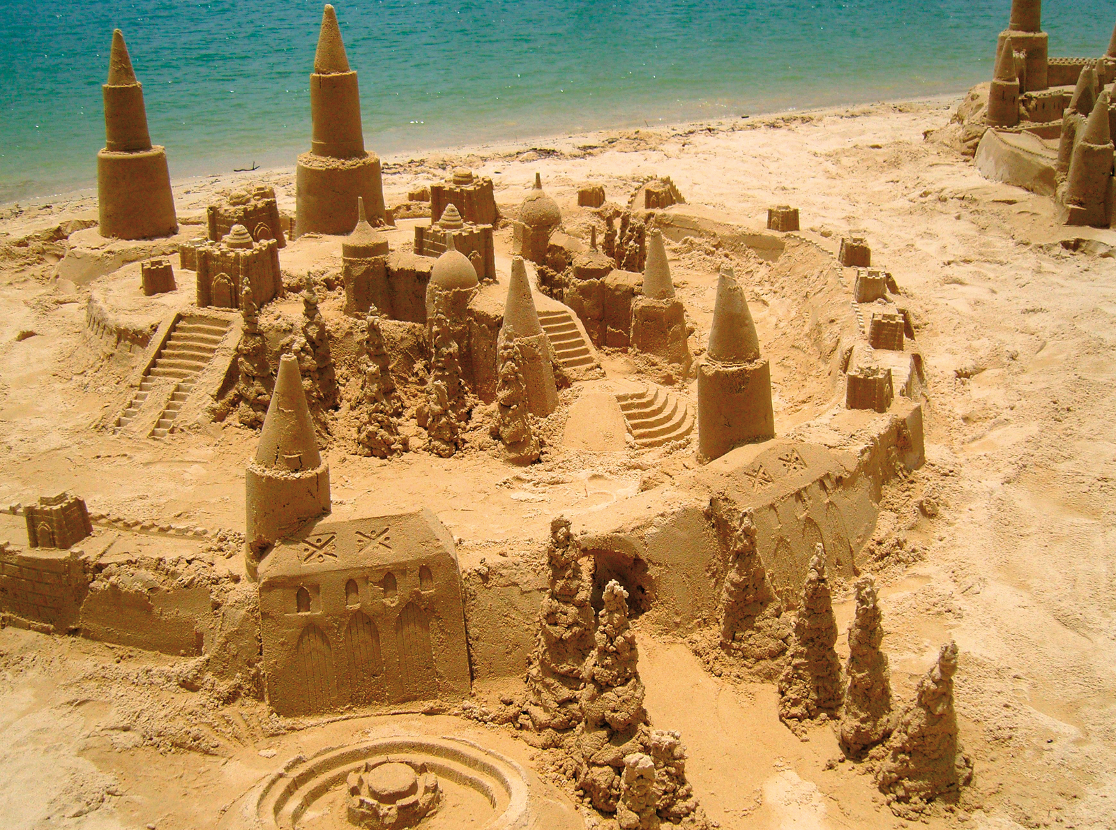
But water is not the only natural phenomenon that presents an interesting challenge to 3D software developers. The BlendaX project [1] at the University of Bremen, Germany, is working on the task of creating a virtual sandbox on standard home PCs using simple resources. The project relies entirely on open source tools. In addition to Blender [2], the toolset includes the free Eclipse [3] developer environment and the Lightweight Java Game Library (LWJGL [4]), which includes OpenGL [5].
A study of the sand problem offers an interesting glimpse at the challenge game developers face in creating realistic visual effects that are still fast enough for an interactive application.
If you want to build a sand pit in your garden, a simple construction of wooden boards and a couple of nails will do just fine, but representing sand on a computer is far more complicated. Presenting each grain of sand as an individual particle in a volume model with three dimensional pixels (voxels) takes more memory and computational power than a normal computer can offer.
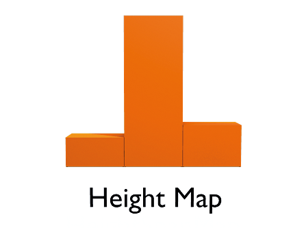
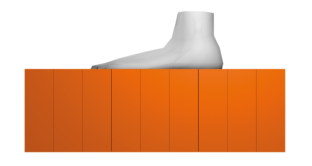
Alternatives all have their weaknesses. Computer games tend to generate surfaces from a simple height map, a two-dimensional table. Just like a bitmap graphic, its cells contain the height information for the position. Many programmers actually implement height maps as grayscale bitmaps: the lighter the color, the higher the floor, and the darker the color the deeper. Surfaces like this can be painted with the use of a fairly basic drawing program. However, a height map is insufficient for representing interactive sand because it only represents a single plane, not the volume of the sand or different layers of the substrate (Figure 1).
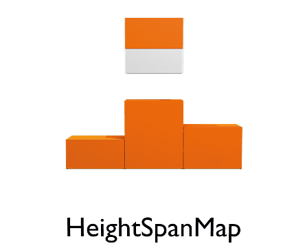
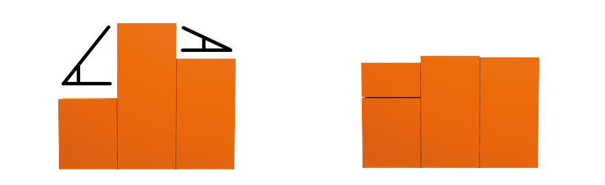
Height Span Maps (Figure 2), as proposed by Onoue and Nishita [6], provide a solution. The idea of a height span map is simple but ingenious. Instead of just containing height information, each cell in the table contains a height span: a column of individual layers of substrate at a specific position. The individual segments contain not one but two pieces of height information - a starting point and an end point. And you can specify the type of material; for example, sand, solid rock, or even air.
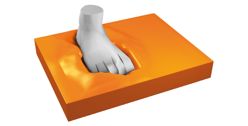
To begin, you need a data structure to represent an object that moves through the sand and influences it - such as a spade or a foot (as used here). To represent the object, the software draws a bounding box around the foot model; this box describes the smallest possible square into which the complete foot model will fit. The X and Y coordinates of the bounding box specify the height spans that could contain foot segments.
The next step is ray casting (Figure 3); the ray-casting technique (used by tools such as Blender) casts a ray through each column.
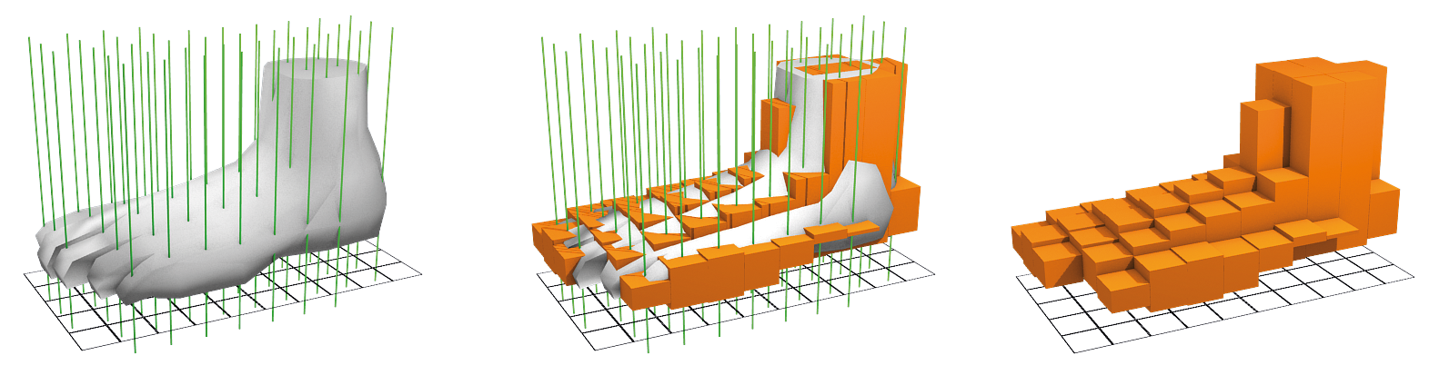
If the ray and the foot model intersect, a new segment is added to the column. The segment with the foot is thus assigned start and end points and assumes the properties of the foot model.
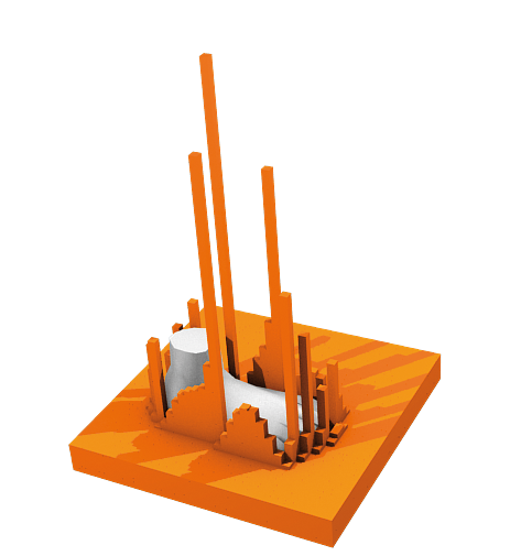
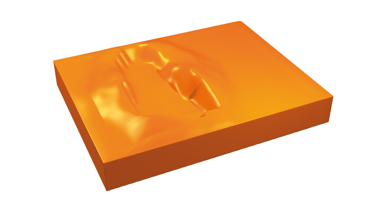
Ray casting doesn't just happen once but is repeated whenever the foot moves, in order to localize the new position. For the foot to leave an imprint in the sand, you need to implement a displacement algorithm that displaces the sand when the foot moves, such that the sand or foot segments of the height span overlap (Figure 4). In this case, displacing sand means subtracting a sufficient quantity from the overlapping segment to resolve the overlap (Figure 5).
The programmer then needs to add the same amount of sand to one or multiple neighboring target segments (Figure 6). If there are no suitable target segments, this means inserting new segments with the right amount of sand into the neighboring height spans. If the foot completely displaces the material, the empty segment is deleted.
Overlapping can occur in two possible ways: horizontally and vertically. If the foot presses into the sand from the top, the laws of physics dictate that the sand is displaced laterally. When this happens, the sand will pile up at the sides of the foot.
For each overlap, the software needs to check whether multiple foot segments are affected by the collision and whether they are neighbors. If the segments involved in this interaction form a contiguous space, the outermost foot segments that overlap with the sand define the contour.
The program can now calculate the distance to the contour for each segment in the area, starting in the center - that is, with the segments that are farthest away from the edge. The next step is to distribute the sand to be displaced - the sand beneath the lower limit of the foot segment - evenly over all neighboring segments defining the contour. This approach pushes the sand from the center to the edge.
A horizontal movement of the foot will not displace the sand evenly in all directions, but mainly in the direction of movement, thus causing a track. With no need to calculate an area or a contour, an overlap between two segments instead pushes the sand in the direction of the movement.
Sand on your feet can be unpleasant; and this is definitely the case for programmers because this covering has to move when the foot underneath it moves. In other words, whenever the foot segments in the height span map move into another span, the software has to check for sand segments immediately on top of it. The sand segments on top of the foot have to move with the foot. If you replace the foot with a spade, you are digging in the sand pit.
So far, these footprints in the virtual sandbox still have a very unnatural shape. Fairly large columns of sand pile up, whereas they should collapse in a heap (Figure 7).
Geologists speak of erosion if external influences such as wind and water remove material. In this case, however, the situation is more similar to the effect of gravity. The mathematical effect is far too complicated to model. Instead, you just want the sand to trickle in a fairly attractive and realistic way without using two many CPU cycles.
Solutions exist for normal, two-dimensional tables. A set of modification rules defines the changes for specific constellations of states in neighboring cells. These models are also referred to as cellular state machines. A typical example of this is Conway's Game of Life [7], in which each cell can assume exactly one of two states: "alive" or "dead." Rules define whether the cell in the middle will die or be reborn at the next step if the eight surrounding cells assume a specific constellation.
A state machine of this kind is perfect to model virtual sand erosion. The rules are comparatively simple: Each cell in a height map contains height information, which the software compares with the eight surrounding cells.
The program calculates the inclination between two cells from the distance and the height difference. This inclination is not allowed to exceed a specific threshold without the excess sand eroding - that is, cascading onto the lower cells. However, sand doesn't trickle in just one direction. The code must first calculate the inclination for all the neighbors and then distribute the excess sand evenly over all the cells with inclinations above the threshold value. A threshold value of 30 degrees provides useful results (Figure 8).
The height span map has eight neighboring columns, each comprising multiple segments that are potential erosion targets. Thus, it is a good idea to find out which of these segments the sand will fall on before calculating the inclination. The program must also account for the fact that sand will fall not only onto other sand segments, but also onto solid rock or other objects in the sandbox. But even that isn't the end of the possibilities: If you apply the rules directly to the height map, each change will influence cells that weren't considered in this round of erosion. In other words, a change in the same round of calculations can have a far greater effect than that for which you have planned, which is why it is important not only to apply the required changes to the right height span map, but also to perform the changes against a copy first. Then, after one round, the copy replaces the original height span map. Instead of giant columns, viewers will now see eroded heaps of sand (Figure 9).
The virtual sandbox is almost complete: The code can move, displace, and erode the sand if a heap becomes too big. But one major piece of the puzzle is still missing: the graphics.
The Lightweight Java Game Library [4] will help create a virtual landscape from the tabular data structure, letting you move an object such as the foot at the press of a button. This library provides the ability to read and process keyboard and mouse input. The OpenGL graphics library included with the package can convert the height span map into a three-dimensional landscape.
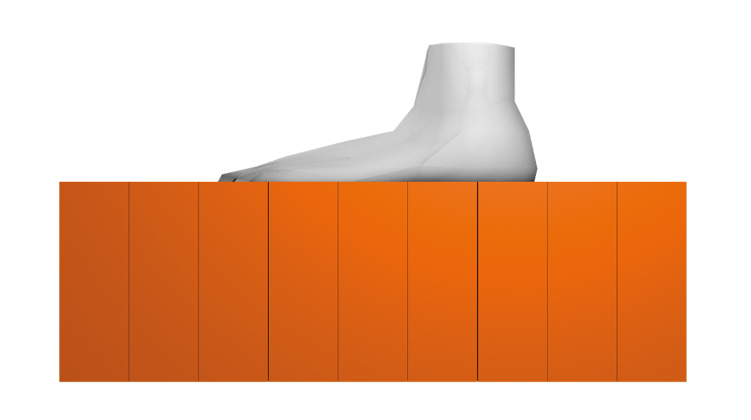
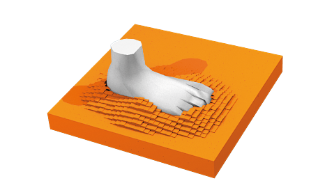
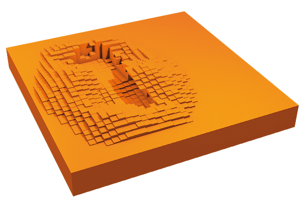
The easiest option for visualizing the results, and the one that is easiest on resources, is a dot-by-dot visualization of the height span map. For each segment, you need to draw a dot to represent the top limit of the segment. Although easy to implement, the results are not particularly pretty, but it is perfect for testing the sand box and identifying errors. Everything is much prettier if you draw a solid block instead of simply dots (Figures 10 and 11).
With the use of different colors, depending on the material, or even textures, the program can achieve pretty impressive results. Of course, the whole thing is still blocky, but you can see whether everything is working properly and clearly distinguish between individual layers and objects.
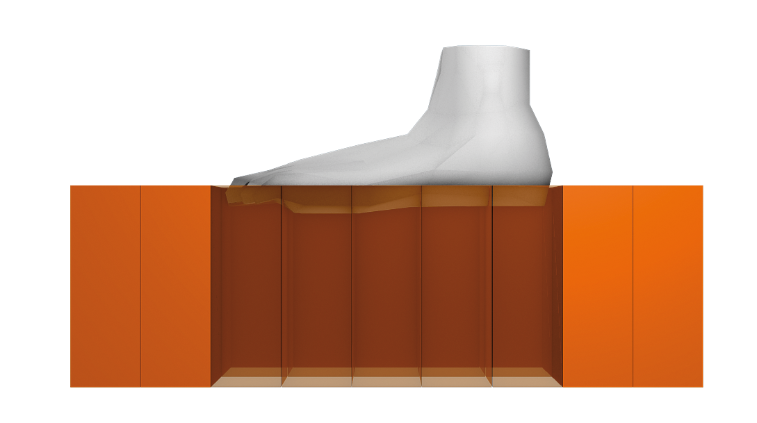
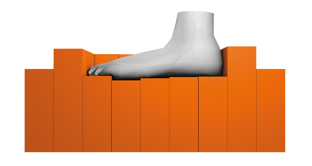
Truly attractive results require a smooth surface, like the surface provided by a normal height map. To achieve this effect, you have to try to subdivide the height span map into separate, contiguous segments by grouping neighboring segments of the same material. The upper limits of the segment in each group can then be joined to form an area, as with a standard height map. This approach can be computationally expensive. The first step is thus to optimize the height span map data structure to find neighboring segments more easily. This visualization ignores the information concerning the sides and base areas of the individual segments.
The problem of smoothing any given area is nothing new. Popular 3D modeling tools offer subdividers that search for contiguous segments of the same material and create a closed area from them (Figures 12 and 13). A subdividing algorithm then divides the large triangles into an area in multiple smaller triangles an arbitrary number of times, shifting the corners so that the surface becomes smoother. Although this approach offers the best looking results, it comes at a price: It is typically too time consuming for a real-time application.
The simulation described here is still young enough to be playing in a sand box. At a certain height span map elevation, an ordinary computer is not fast enough to perform the calculations for the cellular state machine in a reasonable time. Because the visualization relies on subdividers and needs to search for contiguous segments, you can often push a machine to its limits.
Although the results are dramatically faster than those achieved by a particle system, this solution is still in an experimental stage and isn't mature enough for use in computer games. If you want to perform some optimization tests of your own to accelerate the process, you will find the code at the Linux Magazine website [7].
| INFO |
|
[1] Blender: http://www.blender.org
[2] Eclipse: http://www.eclipse.org [3] Lightweight Java Game Library: http://lwjgl.org/ [4] OpenGL: http://www.opengl.org [5] Koichi Onoue, Tomoyuki Nishita, "Virtual Sandbox," Proceedings of the 11th Pacific Conference on Computer Graphics and Applications, p.252, October 8-10, 2003 [6] Conway's Game of Life: http://en.wikipedia.org/wiki/Conway%27s_Game_of_Life [7] Code for this article: http://www.linux-magazin.de/static/listings/magazin/2010/01/ [8] BlendaX: https://blendax.informatik.uni-bremen.de (in German) |