
By James A Barkley
Additive Manufacturing (AM) is the process of joining materials to make objects from 3D model data, usually layer upon layer. Synonyms include additive fabrication, additive processes, additive techniques, additive layer manufacturing, layer manufacturing, and free-form fabrication. Additive Manufacturing represents almost a US$ 2 billion market, with as many as 150 different machines, 50 Original Equipment Manufacturer (OEM) vendors, and 173 materials available for use. The additive manufacturing process is often referred to as 3D printing, although this term is sometimes used pejoratively to refer only to low-cost machines, low-tech machines, or both.
Although the original technologies for 3D printing have been around for at least 20 years, much evolution has occurred in the past five years, and AM technology is leading the charge in the desktop manufacturing revolution. If you have the resources, you can get a high-end AM machine for a minimum of US$ 500,000 (e.g., the Electron Beam Melting units from Arcam Industries) that will produce fully operational parts in titanium super-alloys. At the other end of the spectrum, a number of open source 3D printers have emerged that you can get at cost (some assembly is required).
Open source 3D printing is part of the Open Source Hardware (OSH) movement, in which not only the software is released under open source licenses, but so are the bill of materials (including cost), assembly instructions, firmware, schematics for electrical components, PCB layout data, and any other related information. Some new licenses have been proposed, such as The TAPR Open Hardware License, but many OSH projects tend to simply reuse open source software licenses such as the GPL or LGPL. Personally, I prefer the GPLv3 because of its international protections and "tivoization" clause.
To build a 3D printer, you'll need the following:
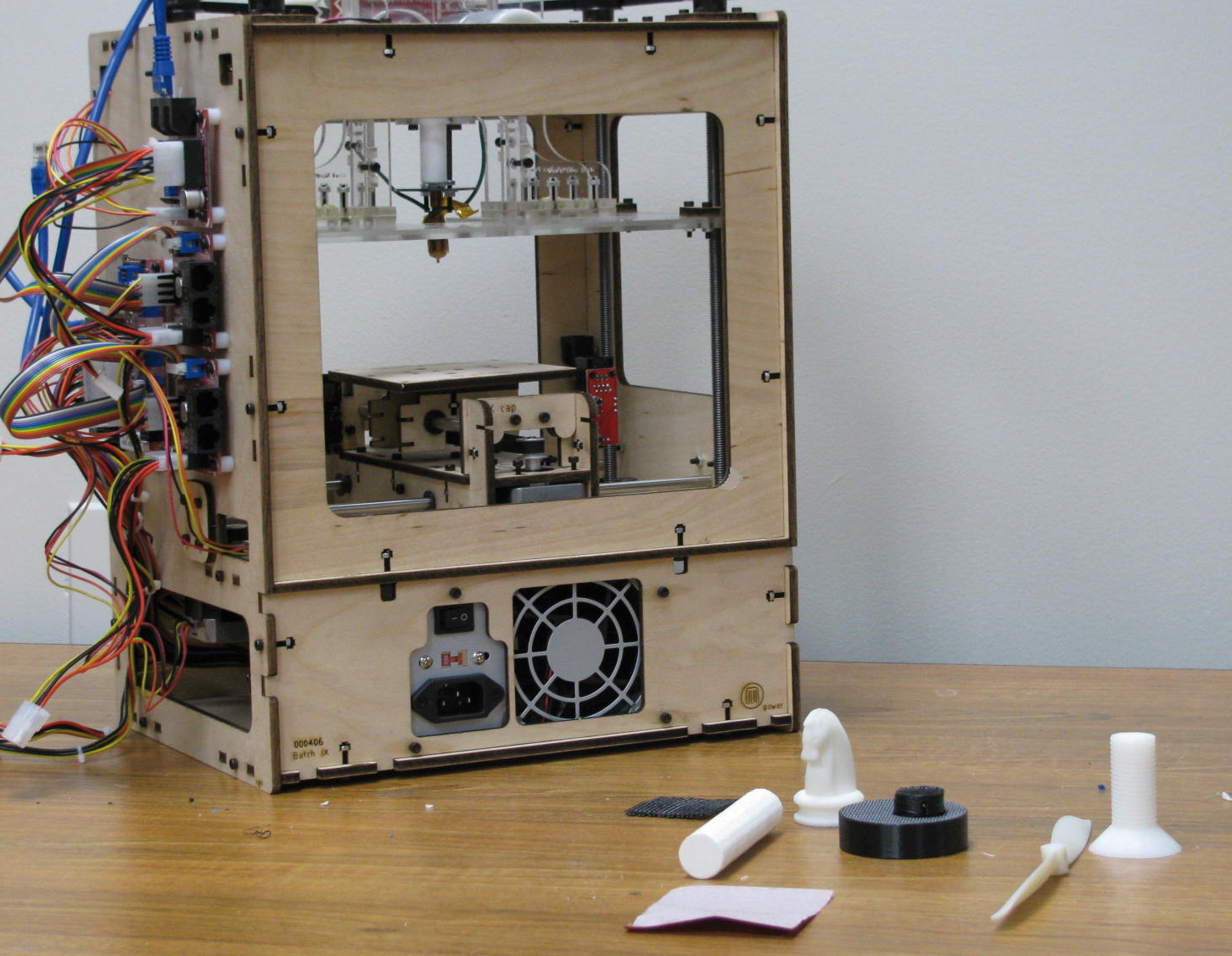
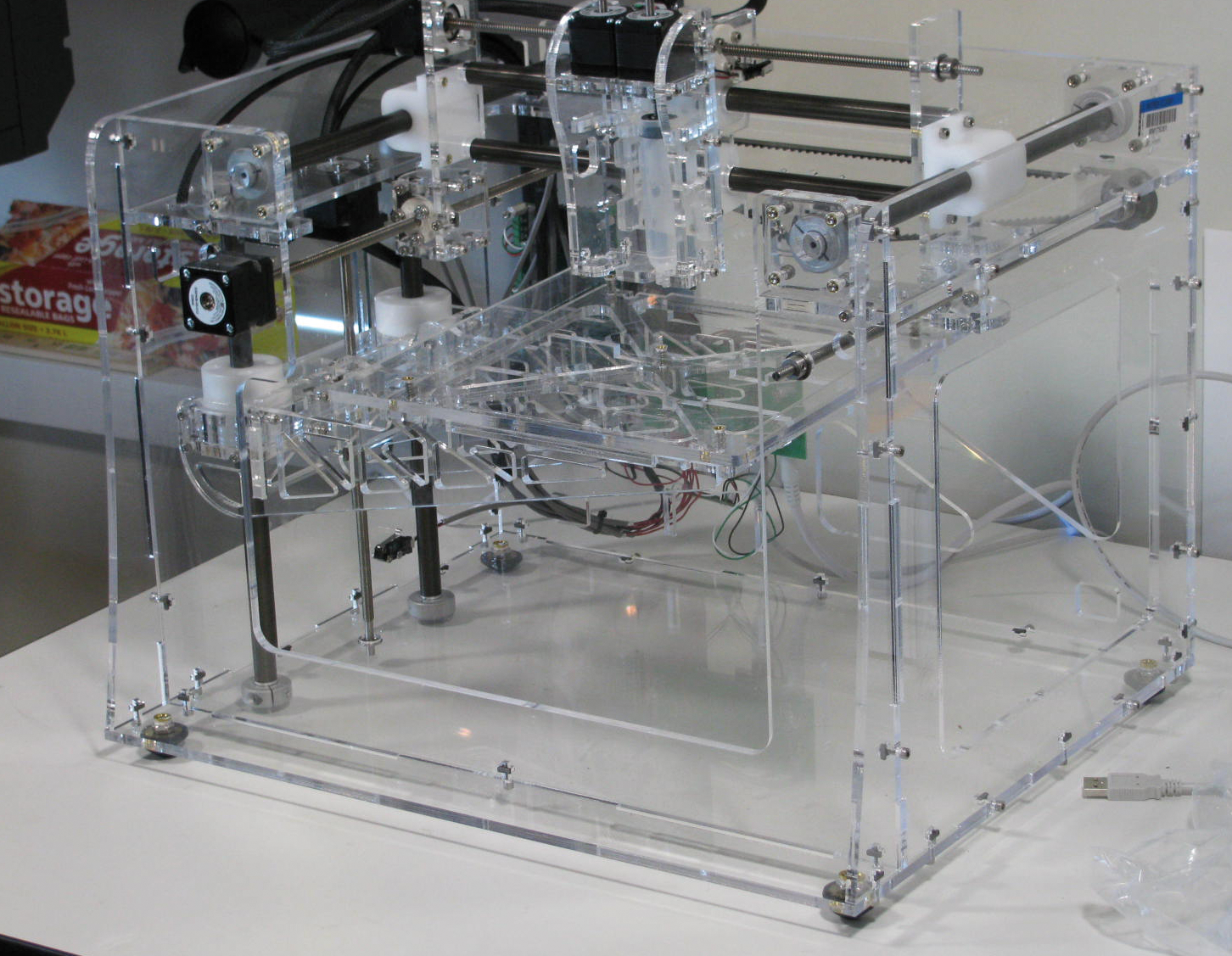
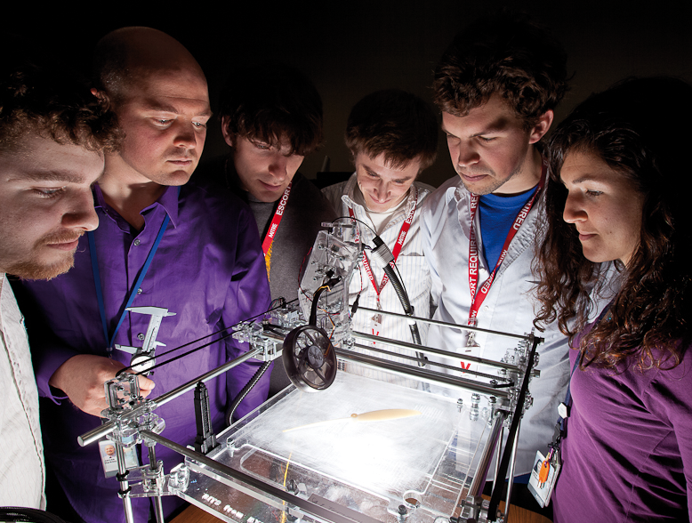
The first step is to select the printer you want to build. The CupCake [2] (Figure 1), Fab@Home [3] (Figure 2), and RepRap Generation 2 [4] (Figure 3) are all good choices. Check out the fact sheets to help you decide, and visit the websites to see which community interests you most. Each printer has various versions, and the latest versions are the best.
Once you select the printer you want, the next choice you have to make is how much soldering, assembly, and general tinkering you want to do. Because these are all open source projects, you can purchase every individual resistor on the published parts list and build it yourself from scratch. At the other end of the scale, you can pay a premium and have someone pre-build the whole thing for you and ship it.
In practice, most people do something in between the two extremes by ordering a kit that has some pre-assembled components, such as the electronics. This is a nice compromise between price and loads of tedious work, while still allowing you to be pretty hands-on and learn in the building process.
Don't be surprised to find that you've forgotten a necessary part, or that the kit you ordered is missing a necessary part. It's easy to lose track of all the pieces you need. And keep in mind that the fledgling businesses that sell the kits are still learning a lot about supply chain management and QA/QC.
| Building a 3D Printer |
|
Many types of Additive Manufacturing technologies exist, ranging from laser beams melting metal powder to inkjet-like spraying of material, which is then UV-cured. The open source genre of 3D printers all use the same general form of the technology, which is often referred to as extrusion or thermoplastic extrusion. This simply means they heat a material past its melting point and then squeeze it through a small nozzle to deposit it. Usually it will cool quickly and another layer can be printed on top of it. This process is similar to glue guns, soldering, and even welding, but it is machine-controlled, which is key. The main parts of this type of 3D printer system are:
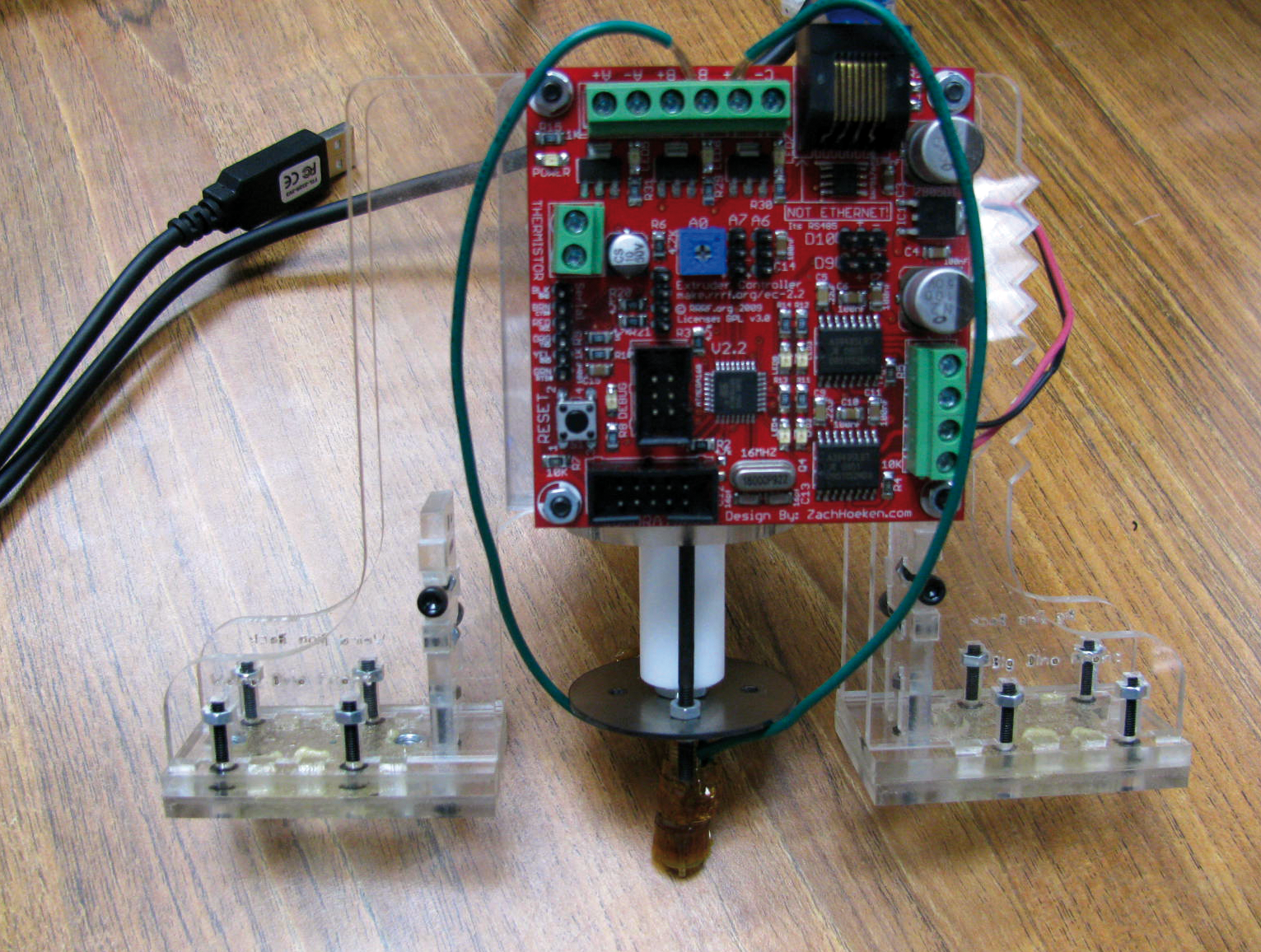
Mechanical construction of the frame and pulley systems will usually be the first thing you do, followed by all of the wiring, soldering, and so on to get the control components hooked into the motherboard. In some cases, each of the x, y, and z motors will have their own control board that will be wired into the motherboard, or else you'll need to wire the motors into the motherboard. After that, you'll want to attach the build platform and assemble the extruder header. At this point, you'll need to flash the firmware to the motherboard and other controller boards and test the components. If they work, then mount the extruder head and take your new machine for a test toast! Don't expect to do this in a weekend. Building a 3D printer from scratch can be an exercise in patience, and a small mistake can set you back a long way. Approach the task methodically and patiently for the best results. |
Depending on which printer you've chosen, your assembly instructions will be delivered with the kit (e.g., the RapMan out of the UK delivers full-blown instructions with animated 3D models demonstrating assembly as a single PDF document), or you will be redirected to a wiki.
A word of warning: Likely, the instructions you encounter will have small inconsistencies, so be prepared to think critically and make your own decisions. The most common inconsistency is that a picture of a particular part in the instructions won't look like your part. Sometimes it's simply because your part is a different color or made of a different material than the part used in the picture. In other cases, it's because the design has evolved faster than the documentation. This has happened to me on numerous occasions, and I realized, "Aha! They're using different corner pieces now for improved stability!"
It is also not uncommon for the electrical, firmware, and software systems to evolve without updated documentation or, in some cases, with special amendments to the documentation, so be sure and check the version numbers printed on the boards and make sure you're using the correct documentation, firmware, and software versions that match them.
In most cases, you'll buy the board with the firmware already installed. However, you might want to be sure or even upgrade your firmware. Additionally, you'll need special software to operate the device, and you might even want to write some of your own control code to interact with the device. Different devices use different software packages and methods for communicating with the device, so it is best to check with the specific device instructions on their wiki sites and forums.
Following are some details about how you would proceed with the software aspects of 3D printing for the CupCake or RepRap devices, which use firmware and software derived from the same source code base. You can print to a CupCake and RepRap device via Windows, OS X, or Linux, but the examples below assume Ubuntu 9.10, Karmic Koala, on x86 hardware with kernel version 2.6.31-20.
First and foremost, you will need the correct connector to talk to the device. Some 3D printers use serial, some use USB, but one of the most common ways of talking to the board is a USB-to-serial cable, which you should be able to find pretty easily.
You will need to download and install the following tools:
To communicate with the device, you will need an AVR programmer, such as the USBtinyISP six-pin connector from LadyAda [9] or Adafruit [10].
Additionally, you might need a few other tools, such as git, sun-java, avrdude, and ftdi_sio and usb_serial kernel modules installed and loaded. Some of these extra libraries are necessary for emulating a serial interface on a USB device. You will find instructions for compiling avrdude online [11], but I was able to get going with:
apt-get install sun-java6-jdk gcc-avr avr-libc avrdude libusb libftdil libtfdi-dev
Because the processor initially can only execute code found in ROM, you will need a bootloader whose only function is to load the firmware (or operating system) from non-volatile memory. Burning the bootloader is as simple as plugging the USBtinyISP into your computer's USB port, plugging the USBtinyISP into the RepRap motherboard, opening the Arduino software, selecting the sanguino option in boards, and then choosing the menu option Tools | Burn Bootloader | w/ USBTinyISP. The Arduino software will tell you whether or not it was successful.
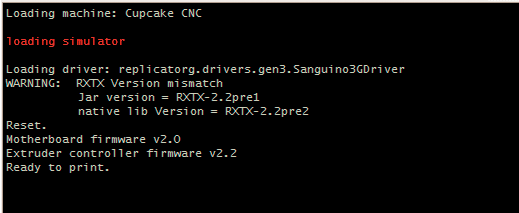
Now that you've got all the software installed and the bootloader burned onto the motherboard and plastruder, you'll want to make sure you can access the printer through ReplicatorG. If you've installed it properly, you should just be able to move to the install directory and run the executable from the command line:
~/replicatorg-0014/> ./replicatorg
If all has gone well, ReplicatorG will open up, and you will see something similar to Figure 5.
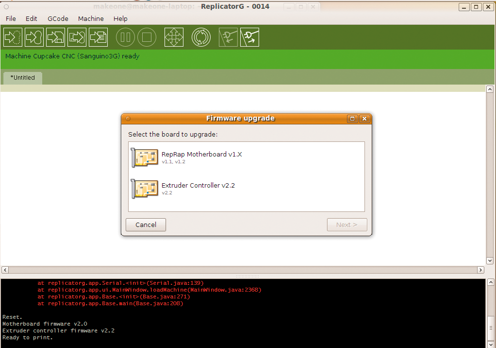
To upload the latest firmware, just open up ReplicatorG and select Machines | Upload New Firmware... from the menu. The wizard will step you through the process; select the board version, firmware version, and USB port, then hit the Upload button (Figure 6).
Once you've got the firmware uploaded to both the motherboard and the extruder board, you can use ReplicatorG to test it by giving it simple instructions such as moving the build platform along an axis.
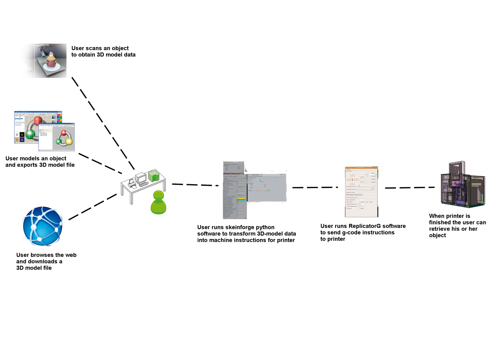
After your printer is working and has been tested, you'll want to start printing. Figure 3 shows a schematic view of the 3D printing process. The first step is to obtain a model of the data you want to print. The three possible options for obtaining printable model data are:
The .stl format (short for stereolithography) is the traditional file format for 3D printing. This format is basically a simple triangle mesh. A sample .stl file is shown in Listing 1. However, you can also use files in other formats, such as .gts, .obj, or .svg.
If you're interested in setting up your own internal website for model tracking, sharing, and printing, you might want to check out the MakeOne open source project [14], which has the goal of one-click printing from a website across a network.
| Listing 1: Sample .stl Code for a Tetrahedron |
01 solid cube_corner ; tetrahedron.stl file definition 02 facet normal 0.0 -1.0 0.0 03 outer loop 04 vertex 0.0 0.0 0.0 ; vertices listed following right-hand rule 05 vertex 1.0 0.0 0.0 06 vertex 0.0 0.0 1.0 07 endloop 08 endfacet ; an implicit check is to compute the normal from the vertices 09 ; and compare it with the normal listed 10 facet normal 0.0 0.0 -1.0 11 outer loop 12 vertex 0.0 0.0 0.0 13 vertex 0.0 1.0 0.0 14 vertex 1.0 0.0 0.0 15 endloop 16 endfacet 17 facet normal 0.0 0.0 -1.0 18 outer loop 19 vertex 0.0 0.0 0.0 20 vertex 0.0 0.0 1.0 21 vertex 0.0 1.0 0.0 22 endloop 23 endfacet 24 facet normal 0.577 0.577 0.577 25 outer loop 26 vertex 1.0 0.0 0.0 27 vertex 0.0 1.0 0.0 28 vertex 0.0 0.0 1.0 29 endloop 30 endfacet 31 endsolid ; end tetrahedrons.stl |
Once you have the part file you want, you need to convert it to specific machine instructions called a build plan. The build plan defines the step-by-step mechanical instructions needed by the 3D printer to execute the part, which includes things like build orientation. For instance, if you are printing a rectangle, the printer needs to know whether to build it with the longer side as width or as height. Another problem is size. Many formats such as .svg and .stl are unitless, so you'll have to determine the dimensions as part of the build plan.
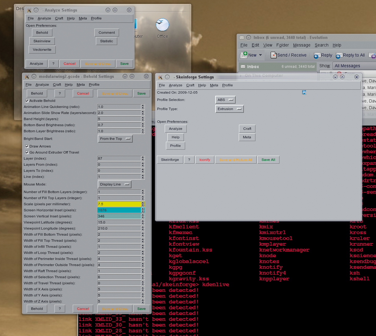
A great open source tool chain for assisting with the build plan is Skeinforge, a set of Python scripts with a basic Gtk interface that allows you to perform a series of translation steps on a model - from carving out inner areas to writing out a set of build plan instructions. Skeinforge has a lot of parts, and it can be configured to use certain profiles for particular machines, materials, and manufacturing processes (e.g., extrusion, milling, etc.). Check the Skeinforge documentation [15] for all of the commands available, or visit the MakerBot site [16] for a good tutorial on Skeinforge configuration. You can use Skeinforge (Figure 8) by simply invoking it from the shell:
/data1/skeinforge> python skeinforge.py
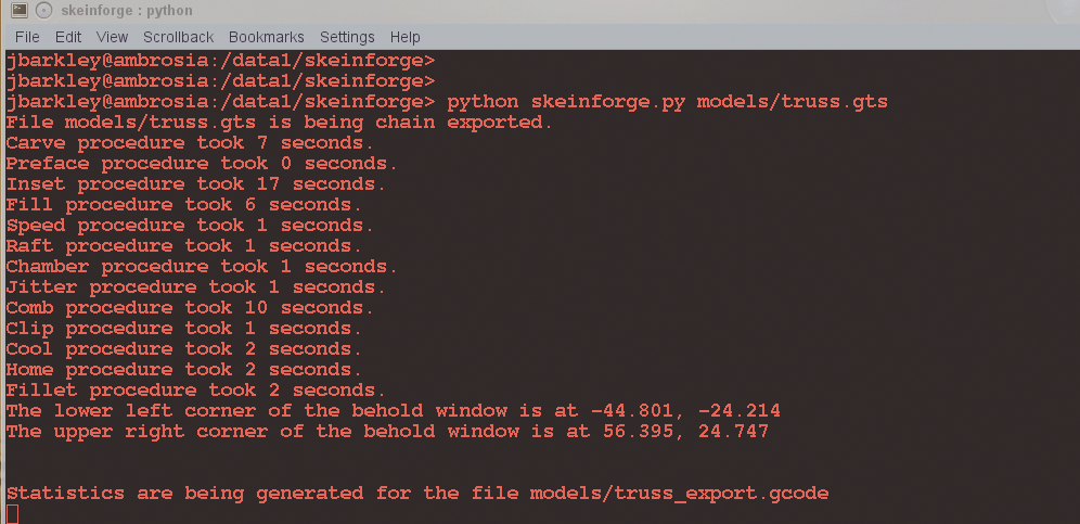
Once you are comfortable with the process, you might want to automate it by running it through a variety of special commands with the available flags. Even if you invoke it on a particular file, the default behavior is to translate it into an instruction set automatically (Figure 9).
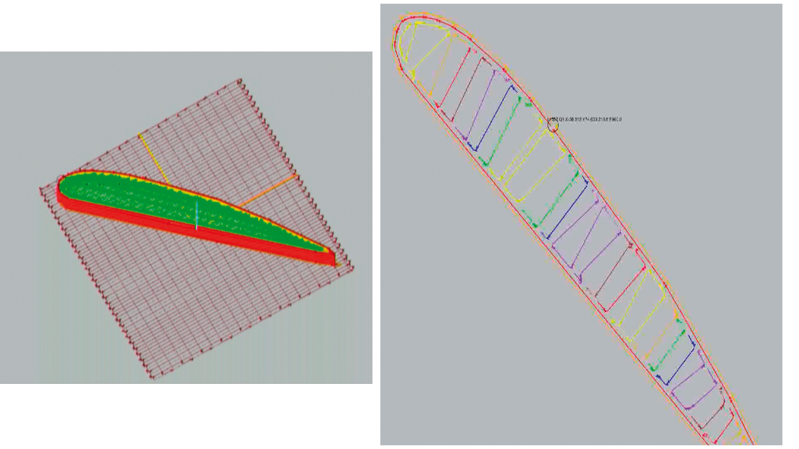
An example of a build plan for a modular wing in both 2D and 3D is shown in Figure 10.
The actual build plan for the RepRap or CupCake will produce a G-Code file [17] [18], a very simple instruction set for machining that has been used in CNC machines. It provides basic one-line instructions for manipulating x, y, and z coordinates, determining the speed of movement, and homing the toolhead. It is called G-Code because each instruction begins with a G and a number defining a specific instruction. (In practice, M-Codes are also mixed in for handling management functions, such as setting the extrude rate and the temperature of the extruder head). You can edit G-Code files by hand, but manual editing gets tediously quickly because there are so many precise x, y, and z movements in almost every single object. Listing 2 shows a sample G-Code listing. Once you've written or generated your final G-Code instructions, load the instructions in ReplicatorG or your printer software and print.
| Listing 2: G-Code Listing for Modular Wing |
01 G90; (absolute programming) 02 G21; (using mm) 03 M103;(turn off extruder) 04 M106;(turn fan on) 05 M108 S210.0; (set extruder speed to S value/10 = 21RPM) 06 M104 S235.0; (set temperature to 235.0 C) 07 G1 X-96.32 Y-0.21 Z0.72 F240.0; (Coordinated motion using linear interpolation to 08 absolute position x,y,z with speed F in mm/minute) 09 M101 10 G1 X-96.32 Y95.68 Z0.72 F240.0 11 G1 X-96.06 Y95.93 Z0.72 F240.0 12 G1 X-91.77 Y95.93 Z0.72 F240.0 13 G1 X-91.52 Y95.68 Z0.72 F240.0 14 G1 X-91.52 Y0.04 Z0.72 F240.0 15 G1 X-91.26 Y-0.21 Z0.72 F240.0 16 ... |
Once your printer is online and printing smoothly, don't expect it to stay that way. Most machines require routine maintenance and recalibration. Many things can go wrong, at which point, forums and blogs are your best bet.
Most importantly, be proactive in tightening the belts around your pulleys and periodically checking all your bolts and nuts. A lot of mechanical vibration can be generated moving the printhead and build platform around. Also, it is important to make sure you know the material you're working with; if you get it too hot it might burn and gum up your extruder nozzle (cleaning nozzles is not fun). Calibration is also important, especially if you've recently moved your machine. If the extruder nozzle is 1mm too close to your build platform, the material could burn ruts into it (especially acrylic). If the nozzle is 1mm too far away from the build platform, the material might cool too quickly and not stick.