
Want to learn how to program a microcontroller and set up a home automation system? Read on to learn the basics of Arduino so you can get started.
This article should acquaint you with basic Arduino programming and show you how to write programs that interact with objects in the real world. (A mandatory disclaimer: the last time I really studied electronics was way back in high school, so this article focuses more on the programming aspects, rather than the electronic side of things.)
Before I start talking about this really cool thing called Arduino (Italian for “good friend”), let me say a few things about the fascinating subject of physical computing. Physical computing has been defined in various ways, but the central idea seems to be the same: physical computing is concerned with developing software that interacts with the world beyond the host computer through a combination of hardware and software—it's aware of the world, so to speak. Such awareness makes these applications capable of sensing external events and responding to them in a predefined way. This is accomplished by the use of sensors and actuators (which I describe next).
The Arduino interacts with the world through actuators and sensors. Sensors are electronic components that describe the world to your application. One common way sensors work is that their electrical properties change (in a mathematically known way) as an effect of the changes in the conditions in which it's operating. For example, the resistance of a photo-resistor changes when the intensity of light incident on it changes. Thermistors are another example of such sensors whose resistance changes when the operating temperature changes. A flex sensor is a different category of sensor, where the resistance changes depending on the extent of the flex or “bend”. Such changes can be read as electrical signals on the Arduino's input pin. Depending on the kind of sensor, the signal either can be digital (on or off) or analog (a continuous stream of values). The latter part of this article shows how to work with analog sensors.
Actuators, on the other hand, are electronic components that are used to react to an external event. For example, when it gets dark, the light should be switched on. Sensors and actuators, thus, are used to achieve complementary objectives: one senses, and the other reacts. Examples of actuators are solenoids and servos. Later in this article, I explain how to control a servo using Arduino.
The Arduino is an open-source electronics prototyping platform composed of two major parts: the Arduino board (hardware) and the Arduino IDE (software). The Arduino IDE is used to write the program that will interact with your Arduino and the devices connected to it. In the Arduino world, such a program is called a sketch, which has its origin in its mother language, Processing (see Resources).
The Arduino board is a small-form microcontroller circuit board. At the time of this writing, a number of Arduino boards exist: Arduino UNO, Nano, Mega, Mini, Pro and others (see Resources for a complete list). The Arduino UNO (Figure 1) is the latest version of the basic Arduino board, and you need one of these to follow this article (see Resources for the UNO's detailed specifications).
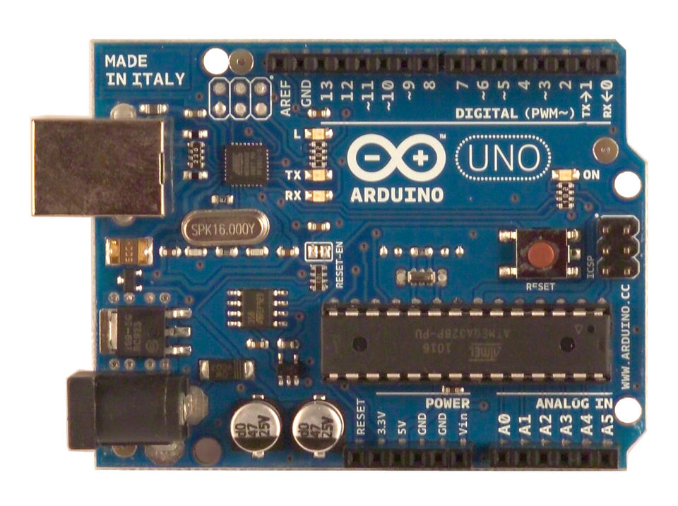
Figure 1. Arduino UNO (Courtesy of arduino.cc/en/Main/ArduinoBoardUno)
Besides the UNO, you need the following hardware to work through this article:
Breadboard to set up the circuit.
Some LEDs.
Resistors: 330 Ohm (at least as many as LEDs), 10 kOhm resistors.
Continuous rotation servo (SpringRC SM-S4303R continuous rotation servo: www.robotgear.com.au/Product.aspx/Details/482).
Flex sensor.
Linear potentiometer.
Connecting wires.
One excellent way to get started with Arduino is the Arduino starter kit from Sparkfun. This starter kit contains all the hardware and more that you need to follow this article (except the servo).
If you haven't already opened up your Arduino and plugged it in to your USB port, plug it in. For the purposes of this article, it will be sufficient to use the power supply via the USB connection. If you connect more devices, you will need to connect an external supply.
You will program the Arduino in a language that looks very similar to C and is based on Processing. You can download the Arduino IDE from the Arduino Project Web site.
As you might guess, the IDE is as always the front end. The real pieces are the compilers, linkers and libraries that need to be present to communicate and program the AVR microcontroller-based Arduino. Depending on your Linux distribution, the exact names of the packages will vary, so I just list the software by name here:
The GNU C and C++ compiler for AVR.
AVR binutils.
AVR libc.
avrdude (a program for uploading code to the microcontroller board).
rxtx (for serial communication).
Once these packages are installed, fire up your Arduino IDE. Take a moment to explore the IDE. The buttons for compiling (verifying) and uploading the sketch are the important ones.
The communication between your computer and the Arduino will be via the USB cable that has been packaged with your Arduino board. Once you plug the USB cable in to your computer (with the other end plugged in to the Arduino board), it should show up in the Arduino IDE under Tools→Serial Port as /dev/ttyACMx. If you have more than one USB serial device communicated, be careful to select the correct one. You need to set up user permissions correctly to access the serial port (see Resources for distribution-specific instructions).
For the first sketch, let's blink an LED and then extend it to blink multiple LEDs alternately. Before the software part, let's first set up the circuit to connect the LED to the Arduino. The completed circuit should look like Figure 2.
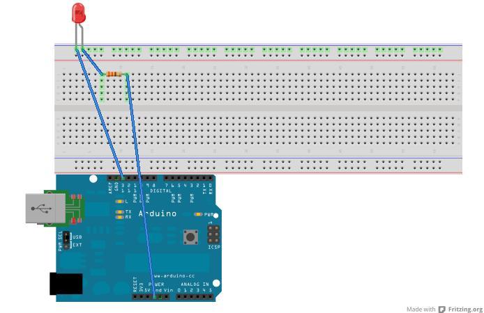
Figure 2. Circuit for a Single LED Blink
Next, in your Arduino IDE, open the sketch in Examples→Basics→Blink, which should look like Listing 1.
As you can see from that sketch and the circuit diagram, the LED is connected to the digital pin 13 of the Arduino. Once you verify (compile) the sketch and upload it to the Arduino board, you should see the blinking LED.
Because this is your first sketch, take some time to understand the general framework of an Arduino sketch. If you are familiar with C or C++, you will notice that you have two functions in this sketch: setup() and loop(). The code that you write in setup() is meant for initialization and is executed once the sketch is uploaded to the board. The code in loop() is executed repeatedly as long as the power to the Arduino is supplied. Even if you power off the Arduino and power it back on, the sketch still resides until you overwrite it with another sketch. An Arduino sketch should be saved in a file with the extension pde and is stored in a directory of the same name.
For the next sketch, let's connect multiple LEDs and blink them alternately to create a cool rippling effect. (You might want to connect more than three LEDs of different colors.) The circuit for this sketch is shown in Figure 3.
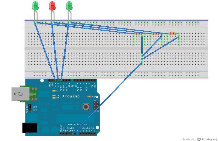
Figure 3. Circuit for Multiple Blinking LEDs
Once you have uploaded this sketch to your Arduino UNO board, your LEDs should put on a colorful performance.
In the first sketch, you turned the LED on and off by writing to the Arduino's digital pin. What if you wanted something in between—say, to fade on and off? Say hello to a tiny little device called a potentiometer. To set up the circuit, connect the central pin of the potentiometer to the analog pin 0, and the other two pins to the +5V supply and ground, respectively. The LED should be connected as in the first sketch.
In Listing 3, you can see that the reading from the potentiometer is used to control the delay time, so the effect of fading in and out is produced.
Next, let's use an electronic component called a flex sensor to (you guessed it) control an LED. Basically, let's use the flex sensor in place of the potentiometer of the earlier circuit. A flex sensor is an analog sensor whose resistance changes with its bending angle. You will see that the resistance changes as you bend on either side—increasing on one side and decreasing on the other. The Arduino sketch is shown in Listing 4.
The flex sensor has two pins: one end should be connected to the +5V input, and the other pin should be connected to the analog pin 0 and farther on to the ground via a 10 kOhm resistor.
All the sketches so far have made use of the Arduino library calls to read and write to the Arduino pins. You haven't directly made use of the serial communication between the host computer and the Arduino board. First, I'll describe how to write a basic client/server style program.
The “server” program is a sketch that lives on the Arduino board waiting for serial data to be available (an integer in this case) and sends back the number by adding 1 to it to the “client”.
To run the client, download the processing IDE and create a new sketch with the code as shown in Listing 5. Run this code after you have uploaded the server sketch (Listing 5) to the Arduino.
Now, let's make things move with your Arduino code. For this example, let's control the movement of a servo—that is, start and stop the servo and control its speed and rotation. Three wires protrude out of the servo: control (white/yellow), power (red) and ground (black/brown). First, set up the circuit such that the the control wire is connected to the Arduino's digital pin 2, the red wire is connected to the Arduino's 5V input and the black wire to the ground. Now, upload the sketch (Listing 7) to your Arduino. You also optionally may connect an LED to the digital pin 13 (in the same way you connected a single LED earlier), which will turn on or off depending on whether the servo is rotating.
Once the sketch is uploaded, open a serial communication channel using screen (feel free to substitute it with your favorite terminal communication program). Type screen /dev/tttyACM0 9600, and you should see the “servo prompt” at your service:
Arduino Serial Servo Control
Keys:'(s)lower' or '(f)aster', spacebar to center and o to stop
Pressing the keys to the servo should produce the desired behavior. If you see the code listing for the servo mechanism, you will see that the key to controlling the speed is basically the duration of the delay (variable pulseWidth) between sending a HIGH and LOW signal to the servo. Here, we are simulating an analog behavior using the important technique called Pulse Width Modulation, which you can read about elsewhere.
If you have gotten this servo example up and running, you also might want to check out the other example sketches for working with servos in the Arduino IDE under File→Examples→Servo.
I'm drawing toward the close of this article, and I hope you have had a lot of fun. However, if you are like me, you already have started wondering what's going on behind the scenes—the journey of the processing sketch to the bytes getting executed on the Arduino board.
The real work behind the scenes is done by the GNU C/C++ compilers, linkers and libraries for the AVR microcontroller. If you hold the Shift key when you compile your sketch, you will see that the commands - avr-g++, avr-g++, avr-ar and avr-objcopy are invoked. First, your Arduino sketch is converted to a suitable C++ file (with the .cpp extension), which then is compiled, linked and finally converted to the hex file that is uploaded to the Arduino board. You can see all these intermediate files in the /tmp/build*.tmp directory. Knowledge of this build process can enable you to bypass the IDE for your Arduino development by writing an appropriate Makefile. See the “Command-Line Arduino development” article listed in Resources for an example.
I've described a few simple but cool things that can be done with an Arduino, but this article barely scratches the surface. A number of excellent books are available that list a great number of Arduino projects you can build for fun and profit. These are, of course, in addition to all the excellent on-line resources available. During exploring Arduino purely from the various blog posts on the Web and a trial-and-error-based approach to learning, I discovered many great projects in the Arduino ecosystem. Be sure to see the Resources for this article for some of the most interesting Arduino books, articles and projects.
Also note that wires are good, but only when you want to limit yourself to the confines of your tabletop or even your room. If you want your Arduino to be out there, decoupled from your host machine, you need to explore ways of wireless communication. Say hello to XBee modules, which allow communication with the ZigBee communication standard.
And before I end, you might face issues with erratic serial communication. Especially during extended periods of experimenting with serial communication, I found that the serial ports would remain locked or just be plainly not accessible from the host computer. My advice is to be patient. Unplug and plug back in a few times, and try killing the lock file manually. Now, you should be good to go.
Thanks to the awesome Arduino community members for their documentation and numerous other bloggers on the Web. The Arduino circuit diagrams were drawn with Fritzing (fritzing.org).
