
Rock your stage lighting with a Raspberry Pi light controller.
I am the proud parent of twin 13-year-old rock-star daughters. They are seriously good musicians, and of course, I taught them everything they know. The girls typically perform indoors “coffee-house” style or outdoors in the daylight. But, this fall, the girls booked a number of outdoor gigs in the evening. This meant we had to have stage lighting. After a quick trip to the local music instrument supercenter—where they know us by name—we had all the lights, stands and trusses we needed for a good night-time show. The light system we purchased had many useful built-in options for creating light shows: various color chase sequences, variable strobe speeds and sound-activated or fixed-time sequencing. These are great options. But, if you are looking for maximum wow-factor from a performance, you want to have direct control over the light system.
Lighting control hardware is available to control your stage lighting. In addition, several commercial and open-source software lighting control packages work with many off-the-shelf lighting devices. Some of these, such as QLC and QLC+, are available for Linux. Many of the software light controller packages are based on the Open Lighting Architecture (www.opendmx.net/index.php/OLA). If you are looking to set up a professional light show and need to control several complex devices, such as movable lights, one of these options is probably the way to go.
I am the sound guy/roadie/driver/financier for this band. So I figured, what could it hurt to add lighting control guy to my résumé? Given my other duties during the show, I wanted something pretty simple to operate, with capability to add custom features as needed. Commercial lighting control hardware seemed like overkill for my needs, and I wasn't real keen on dragging a laptop to a show just to control the lighting. This sounded like a good Raspberry Pi project.
When I started investigating lighting control options, I quickly found the language of light control: DMX512. The United States Institute for Theatre Technology created DMX512 in 1986 as a standard to control dimmers on stage lights. The standard has had a few updates since 1986 and is now an ANSI standard. DMX512 uses a multi-drop RS-485 bus for the physical layer signaling. There is a single master device (the controller) and up to 512 slave devices (the lights). The RS-485 differential signaling provides for good noise immunity over the long cable runs needed to control lights that are spread around a stage or arena. Each slave DMX512 device has IN and OUT XLR connections, and devices are daisy-chained together. The last device in the chain should include an XLR stub connector with a 120-Ohm termination resistor. For the girls' stage lighting, we used two Chauvet COLORstrip Mini LED wash lights.
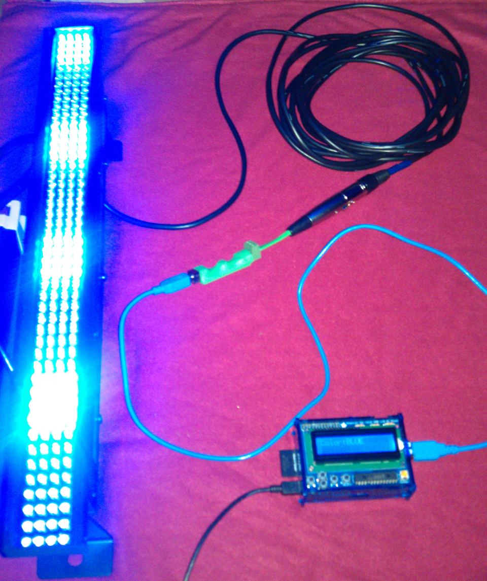
Figure 1. Raspberry Pi DMX512 Light Controller (photo by Jonathan Brogdon)
The DMX512 protocol is very basic. Remember, it originally was designed for light dimmers. The only protocol message, sent by the master, is a block of unsigned byte values (0–255)—one for each “channel”. Each slave device has its own definition of how a “channel” is interpreted. For example, channel one may set the general light mode (fixed color, fixed sequence, random sequence and so on). The second channel may indicate the sequence transition speed (fixed value, sound activated and so on). On the other hand, a very simple device might define the channel values as dimmer values for each light on the device. The manufacturer's documentation will spell out how each channel should be used. The DMX512 protocol runs at a fixed 250k baud rate.
One interesting quirk of the protocol is that messages must be sent continuously. If the master stops sending messages to a device, the lights go out. This also means that once a device receives a message with channel values specifying a particular light sequence, it will run the sequence as long as it keeps receiving messages with the same channel values. For example, suppose the value for channel 1 is 80, which indicates that the color sequence is red, green, blue, yellow, magenta, cyan, white. The value for channel 2 is 10, which indicates that the color should change every ten seconds. If you want to keep this sequence running, the master must keep sending messages with channel 1=80 and channel 2=10.
I found a simple USB-RS-485 converter based on the ubiquitous FT232R USB-Serial chip from Future Technologies Devices International. You can find these for around $20 or less from several sources. I got mine on eBay. I attached a three-pin female XLR connector to the RS-485 I/O pins, and voilà, I had my DMX512 physical interface. The Entec Open DMX USB is another popular option (www.enttec.com/open_dmx_usb). This product also is based on the FT232R chip and comes in a nice sturdy steel enclosure, all for $70. The code in this article works with either option. Note that the Open DMX USB box has a five-pin XLR connector. If you plan on using the less-expensive three-conductor DMX512 cables, you will need to add an XLR five-pin-to-three-pin adapter.
Now, I needed a software interface for sending DMX512 protocol messages. The main task here is configuring the FT232R chip for DXM512 communication at 250 kBaud with eight data bits, no parity and two stop bits. Most Linux distributions have a driver that supports the FT232 family of devices. However, if you are thinking about using the serial device interface presented by the driver (for example, /dev/ttyUSB0), you probably won't get far. Standard utilities like stty will not support setting the 250-kBaud rate. Instead, we need to talk to the FT232R as the USB device that it is.
My language of choice for this project was Python. So, I looked around for Python packages that could address the FT232R chip as a USB device. I found PyFtdi (https://github.com/eblot/pyftdi.git). PyFtdi provides a user-space driver for talking to FTDI devices. The PyFtdi package depends on PyUSB (https://github.com/walac/pyusb.git), which depends on LibUSB (www.libusb.org). I used the standard Raspian “Wheezy” image for this project. So, I was able to install libusb via the package manager. I installed PyUSB and PyFtdi via the setup scripts included with each package. The source for the DMX512/USB interface shown in Listing 1. Note that a DMX512 protocol message must be terminated with two break characters.
The DMX512 controller needed a user interface. My first thought was for a grand Web interface over an ad hoc Wi-Fi network. The plan was to run the UI from a browser on my phone or tablet. But, that would mean more gear to be charged up and dragged to the show. Plus, I've learned (the hard way) to pick reasonably economical solutions for band support gear so you can afford a backup. I decided to use a much simpler UI device: the Adafruit Pi Plate LCD+Keypad. This is a two-line x 16-character LCD with five key buttons: “up”, “down”, “left”, “right” and “enter”. This device is made specifically for the use with the Raspberry Pi, and it plugs in directly to the GPIO header. The Pi Plate uses the Hitachi HD44780 LCD controller. The LCD interface and key buttons are accessed via an i2c I/O expander on the Pi Plate.
Adafruit provides some example Python code for the Pi Plate (https://github.com/adafruit/Adafruit-Raspberry-Pi-Python-Code.git), demonstrating how to write to the LCD and read from the key buttons. This code is great for a single application that controls all the LCD resources. I needed the UI to run automatically when the system boots. I could have adapted the Adafruit Pi Plate example code to run as a dæmon. However, I considered LCDproc to be a better choice (lcdproc.org). LCDproc is the de facto UI framework for embedded Linux systems that support LCDs—with or without keys.
The LCDproc framework is composed of a server dæmon with “drivers” for specific LCD families and physical connection options (that is, parallel, serial and so on). Note that these are userspace drivers that use device interfaces to access the LCD hardware. An LCDproc client application contacts the server over a socket to output to the LCD or read key input. A client can allocate an area of the LCD for its output or map individual keys for its input. For example, you might have a client that displays the system uptime on the left side of the first line, another client that displays the current system time on the right side of the first line, and a third client that displays the IP address on the second line. I liked the flexibility of having multiple LCD clients for future applications. The LCDproc communication protocol uses text strings over a TCP socket connection. This makes for easy protocol debugging.
LCDproc provides a driver for the HD44780 LCD, with several connection options. Unfortunately, LCDproc did not have driver support for the Pi Plate's LCD connection via the i2c I/O expander. So, I decided to add it. See https://github.com/jlbrogdon/lcdproc-piplate.git for the Pi Plate driver patch.
LCDd is the LCDproc server dæmon. The LCDd configuration file contains several server and driver options. By default, the path to this file is /etc/LCDd.conf. For the Pi Plate LCD, the following config options should be used:
[server]

# Where can we find the driver modules?
# IMPORTANT: Make sure to change this setting to reflect your
#            specific setup! Otherwise LCDd won't be able to find
#            the driver modules and will thus not be able to
#            function properly.
# NOTE: Always place a slash as the last character!
DriverPath=/usr/local/lib/lcdproc/

Driver=hd44780

[menu]
# You can configure what keys the menu should use.
# Note that the MenuKey will be reserved exclusively;
# the others work in shared mode.

# Up to six keys are supported. The MenuKey (to enter
# and exit the menu), the EnterKey (to select values)
# and at least one movement key are required.
# These are the default key assignments:
#MenuKey=Escape
EnterKey=Enter
UpKey=Up
DownKey=Down
LeftKey=Left
RightKey=Right

## Hitachi HD44780 driver ##
[hd44780]

# Select what type of connection.
# See documentation for types.
ConnectionType=i2c-piplate

# i2c address for the I/O expander
Port=0x20

# Device of the serial interface [default: /dev/lcd]
Device=/dev/i2c-1

# Bitrate of the serial port (0 for interface default)
Speed=0

# If you have a keypad connected.
# You may also need to configure the keypad layout
# further on in this file.
Keypad=yes

# If you have a switchable backlight.
Backlight=yes

# Specifies the size of the LCD.
# In case of multiple combined displays, this should
#  be the total size.
Size=16x2

KeyDirect_1=Enter
KeyDirect_2=Up
KeyDirect_3=Down
KeyDirect_4=Left
KeyDirect_5=Right
A complete config file is available with the patch.
With the LCDproc server up and running, I could focus on the LCD client side of my light controller. I used the Python lcdproc package (https://github.com/jingleman/lcdproc.git) for the client interface to LCDproc. This allowed the DMX512 light controller client to open a connection to the LCDproc server, set up widgets on the LCD, send output to the widgets and get input from the key buttons. For this project, I used the “up” and “down” keys to cycle through light color options and the “select” key to select the desired color output (Figure 2).
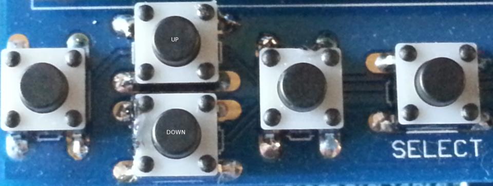
Figure 2. Pi Plate LCD Keys (photo by Jonathan Brogdon)
Listing 2 shows the UI processing for the light controller. This code opens the LCDproc server connection, defines the UI widgets for the LCD, displays the light color options, processes the key button input and updates the UI widgets based on key inputs.
The light controller application is packaged as a Python script with a start-stop-dæmon script to run the application at system initialization. The Python script is shown in Listing 3 and is available at https://github.com/jlbrogdon/dmx_controller.
The application has two concurrent threads: the UI thread and DMX512 controller thread. The UI thread runs the LCDproc client shown in Listing 2. When a new light color is selected, the UI thread builds a complete DMX512 protocol message, with channel values corresponding to the user-selected light color and queues the message to the DMX512 controller thread.
The DMX512 controller thread initializes the FT232R device for DMX512 communication and continuously checks for any new protocol messages from the UI thread. Any new protocol message received from the UI thread is sent repeatedly to the DMX512 slave devices. Recall that when the controller stops sending protocol messages, the slave turns off the lights. Figure 3 shows a collage of the various output colors.
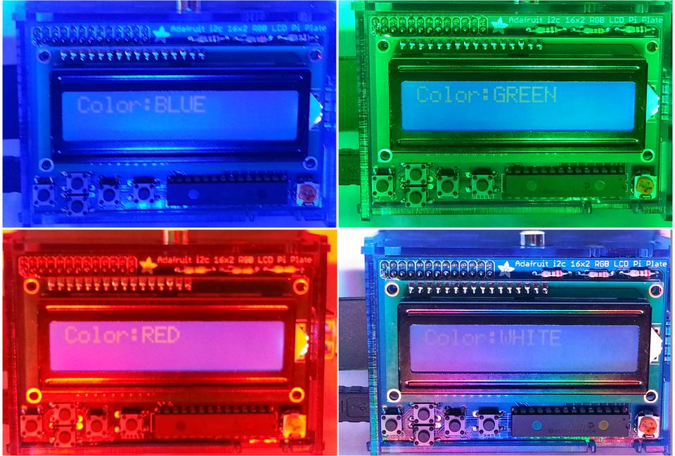
Figure 3. Collage of Color Selections (photo by Jonathan Brogdon)
Many of the DMX512 light control systems available today provide a lot of configurable options for the user, which also adds a learning curve and potentially many more levers for you to pull during the stage show. However, if you are looking for something simple to control a few stage lights for your band, small stage production or holiday lighting display, this Raspberry Pi-based light controller has the benefits of simplicity, extensibility, customization and low cost. One of my ultimate goals is to add a song selection menu and have the controller sequence the lights according to values in a corresponding file. Until then, rock on!
