
The BeagleBone Black is a wonderful little piece of hardware. You could use it to send your next rocket to Mars with just a few lines of Python.
The BeagleBone Black (BBB) is a low-cost, low-power, credit-card size (3.4" x 2.1") board with a lot of features, and it costs about $60. It sports a 1GHz Sitara AM335x ARM Cortex-A8 (an ARMv7) processor from Texas Instruments, 512MB of RAM, and it has all the I/O capabilities you'd expect from a typical microcontroller, such as access to a CAN bus, SPI interface and i2c, analog input, PWM and so on.
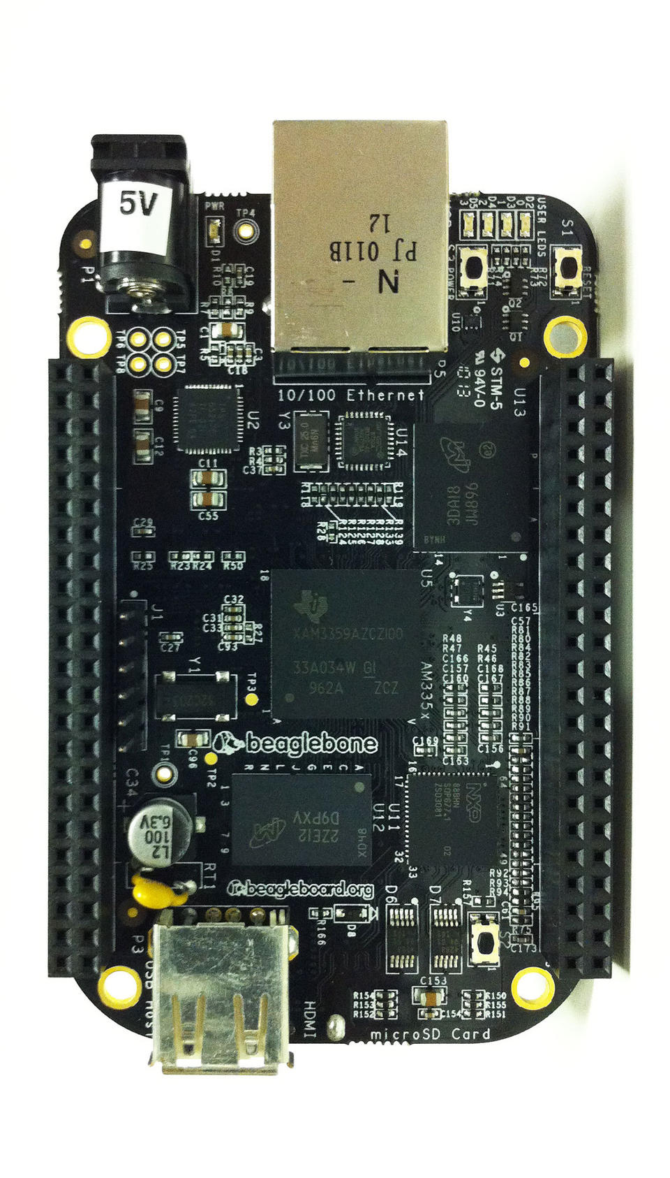
Figure 1. The BeagleBone Black board—isn't she beautiful?
But, the board also holds two PRUs, an HDMI video output, an SD card slot and 100Mb Ethernet. This makes the board a complete ARM PC, fully compatible with Linux. As icing on the cake, Beagle fancies an open hardware philosophy: all of the chips and designs are available to the public.
Right out of the box, you can use it for the following:
A great learning platform with easy access to the connected hardware. You can play with almost all the functionalities from the Web interface with the Bonescript language. Just plug in the board via the USB client on a PC, open the page of the board (http://192.168.7.2) and voilà! (See beagleboard.org/getting-started.)
A light desktop system if you add a 5VDCC external power supply, an HDMI cable, a screen, keyboard and mouse.
This article focuses on working on a BBB from a Debian system with Python and some minimalism in mind. But, this is still a fully-fledged Linux system, not an Arduino or microcontroller.
In this article, I describe how to access some of the I/O ports:
The serial ports, to read and write on devices with an RS232 interface like a GPS, for example.
The GPIOs, which allow you to trap or send TTL signals, drive a relay, read a button status, and in particular, let you add a PPS to Linux.
The analog input voltage for reading voltages coming from a lot of sensors.
Components on the i2c bus: an RTC handled by the system and a DAC driven from your applications.
I finish the article explaining how to use the BBB as a time server, thanks to a GPS.
In our project, the BBB boards are embedded in small compartments, accessible only through a network connection. I chose to configure them with the bare minimum, from the eLinux version. There is no X session, no fancy Web interface, just the good-old command line via SSH, and the applications are launched automatically at boot via /etc/rc.local. They are used in a Unmanned Surface Vehicle (USV), and the interactions with the operator are done through a hardware control panel via a serial line, through Web interfaces and with networked applications. The interactions with the hardware of the USV are done through its many I/O ports, of course.
Do I really need to tell you? Okay, we have enough processing power, so Python equals less code and more readability of the applications, and a lot of useful modules already are available. All code and examples in this article are for Python 2.7, but it would be not very difficult to port it to Python 3.4.
The Debian system:
When we received our BBB boards in September 2013, they were pre-installed with the Angstrom distribution. Thanks to the work of others who were also attached to Debian, I quickly was able to keep playing with my favorite Linux system on my fresh BBBs.
I installed the images provided by eLinux, but you also can fetch an image from armhf: www.armhf.com/boards/beaglebone-black/#wheezy.
Since March 2014, Debian Wheezy (stable) is an official system image available for the BeagleBone Black (rev B and C). For the latest images, see beagleboard.org/latest-images.
You can choose to upgrade to testing (or sid if you feel more adventurous) in order to enjoy more recent software. (See the Upgrading from Debian Stable to Debian Testing sidebar.)
The BBB accepts booting from the internal memory, the eMMC or from an external SD. (See the Booting the BBB from an SD Card sidebar.)
To test another version of the system, simply download and write it on your SD. If you are satisfied with it, you have the option to put it on the eMMC.
As the environment hosting our BBBs is subject to strong vibrations, I chose to put my system in the eMMC rather than on an SD.
Flash the eMMC:
In order to flash your new system to your eMMC, download the flasher version from eLinux or the official one. Write it to your SD and boot your BBB from the SD. The flashing process happens automagically. You will have to wait less than ten minutes before the four blue LEDs become steady, indicating that the flashing is over. As the official firmware is much larger, the flashing will take a lot longer (45 minutes).
Danger: you need to power the board with an external 5VDC power supply when flashing!
In order to use the armhf version, partition and format your SD card following the armhf site instructions at www.armhf.com/boards/beaglebone-black/bbb-sd-install. You then can download a recent armhf rootfs archive (s3.armhf.com/dist/bone/debian-wheezy-7.5-rootfs-3.14.4.1-bone-armhf.com.tar.xz) and copy it to your SD. Then, when booting from the SD, you likewise can copy your SD installation to your eMMC.
As the time of this writing (July 2014), these Debian images come with Linux kernel 3.8.13. This version brought many improvements to accessing the BBB hardware by the kernel via sysfs.
Here is a list of packages I recommend for working with the board from the shell and from Python:
# apt-get install kbd locales htop vim screen \
rsync build-essential git python-setuptools \
cython python-pip python-virtualenv python-dev \
manpages-{dev,posix{,-dev}} glibc-doc- \
reference python-serial python-smbus python- \
lxml python-psutil i2c-tools
For interfacing with a GPS with a PPS:
# apt-get install gpsd python-gps pps-tools \
bison flex git-core
If you want to play with NTPd:
# apt-get install ntp
What Time Is It?
If an NTP server is available to your BBB, good for you, but as the BBB lacks a backed battery RTC, it doesn't retain date and time after reboot, so you will have to take a few measures.
First, enter the date in UTC manually, before anything else:
# date -u 072314512014.30
Wed Jul 23 14:51:30 UTC 2014
If your BBB must be isolated from an NTP server, one solution is to add an RTC to the board, like a ds1307. (I will show how to add one on the i2c bus.)
Finally, if you are isolated and without an RTC module, try the fake-hwclock package from the Debian repositories. It will allow your clock to restart with the last date saved when the system halted.
To DHCP or Not to DHCP:
If your network hosts a DHCP server, you are fine; otherwise, you can configure your network card “static” in order to avoid a big DHCP timeout when you boot your BBB with the Ethernet cable plugged in. (See the Configuring the Network Card Static sidebar.)
A Life Line (Serial Debug):
More often than not, the boards are in a place where we can't have a keyboard and display attached to them. We can work remotely by SSH, but if something goes wrong, we need to access the serial debug interface on the board.
The serial interface available through the USB connection to the board is not ready when you boot with U-Boot—you can't see the kernel starting or intervene. That's why we use the serial debug provided by the J1 connector on the board, referred to as ttyO0 by the system.
As a side note, this serial line can be made available via Ethernet with a cheap RS232↔IP converter if remote boot monitoring is needed.
Before connecting our BBB on a PC via this serial line, we need a TTL↔RS232 converter. See some serial debug references on eLinux at elinux.org/Beagleboard:BeagleBone_Black_Serial. You can purchase a PL2303HX USB to RS232 TTL auto converter module—they are very cheap. Just make sure the end of the cable is made of jumper wires and not a fixed connector (Figure 2).
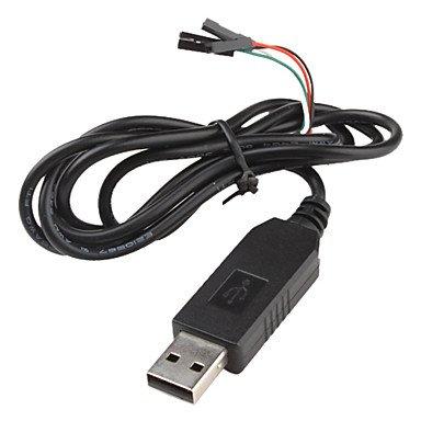
Figure 2. An Essential Accessory—PL2303HX USB to RS232 TTL Converter
This Code Chief's Space page provides a very thorough step-by-step guide: codechief.wordpress.com/2013/11/11/beaglebone-black-serial-debug-connection.
Serial Login into the System:
You probably are familiar with the text consoles with Login: that you make appear with Ctrl-Alt-F{1..6}. We wanted the same, but through our serial debug. So, we configured a tty on the BBB allowing us to connect to it via the serial line when it is booted. Just add this line (if it's not already present) to the end of /etc/inittab:
T0:23:respawn:/sbin/getty -L ttyO0 115200 vt102
And, make sure the kernel knows the correct console on which to output its messages. In the /boot/uboot/uEnv.txt file, it should read:
console=ttyO0,115200n8
#console=tty
Finally, to connect us to the BBB through our serial debug line from another PC with a USB↔RS232 adapter:
$ screen /dev/ttyUSB0 115200
The Serial Ports:
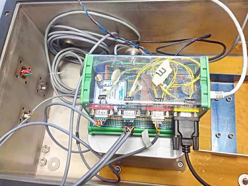
Figure 3. The Board “bbbO2” in situ with three serial ports and the serial debug port, a temperature sensor on AIN0, a water detector on GPIO_48, a PPS input on GPIO_49 and a POWER_RESET button.
As you previously saw, the serial port must be accessed with a TTL/RS232 adapter. In our project, we re-used some old Maxim MAX3232s to do it, and it works, of course, for the other UARTs available on the board.
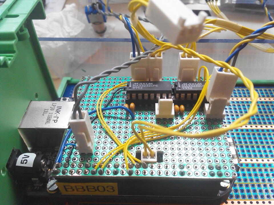
Figure 4. Our CAPE with Two MAX3232s
The BBB comes with six UARTs, but three of them can't be addressed by our applications:
UART0 is the serial debug on J1.
UART3 lacks an RX line.
UART5 can't be used altogether with the HDMI output.
So UART1, UART2 and UART4 are the ones available, and they are addressed, respectively, as /dev/ttyO1, /dev/ttyO2 and /dev/ttyO4. Note that only UART1 and UART4 have CTS and RTS pins.
Load the CAPE files for each UART:
for i in {1,2,4}
do
  echo BB-UART$i > /sys/devices/bone_capemgr.*/ \
slots
done
The output of dmesg should show a correct initialization:
# dmesg |grep tty
...
[    1.541819] console [ttyO0] enabled
[  286.489374] 48022000.serial: ttyO1 at MMIO \
0x48022000 (irq = 89) is a OMAP UART1
[  286.627996] 48024000.serial: ttyO2 at MMIO \
0x48024000 (irq = 90) is a OMAP UART2
[  286.768652] 481a8000.serial: ttyO4 at MMIO \
0x481a8000 (irq = 61) is a OMAP UART4
Now you can ask the kernel to load them at boot time. Edit /boot/uboot/uEnv.txt and modify the line with optargs, like this:
optargs=capemgr.enable_partno=BB-UART1, \
BB-UART2,BB-UART4
Okay, but Does It Work?
To test the serial lines, we just have to connect two of them together (Figure 5).
Table 1. Direct Connection of UART1 with UART4
| UART4_Tx | PIN __13__ of P9 | ↔ | PIN __26__ of P9 | UART1_Rx |
| UART4_Rx | PIN __11__ of P9 | ↔ | PIN __24__ of P9 | UART1_Tx |
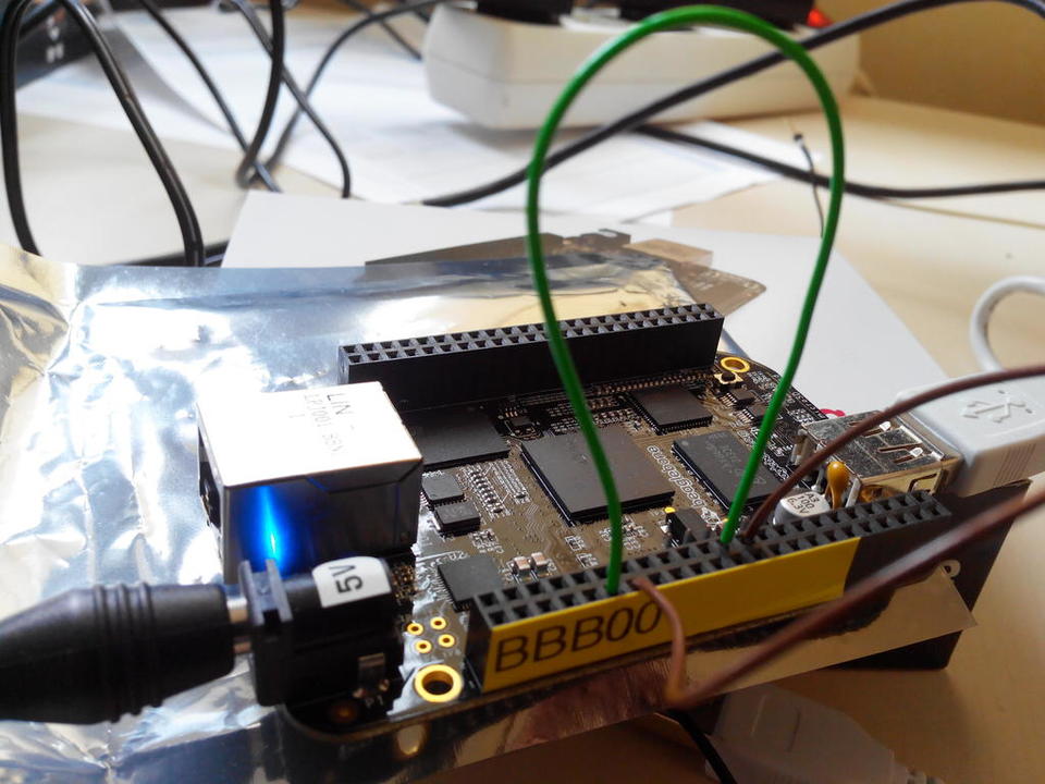
Figure 5. Direct Connection between UART1 and UART4
Now, launch a screen session on UART1 with screen /dev/ttyO1 115200, split your window with a Ctrl-A S, move to the next window with Ctrl-Tab, open a screen on UART4 with Ctrl-A :, then type screen /dev/ttyO4 115200, and check that what you type in one window appears in the other (Figure 6).
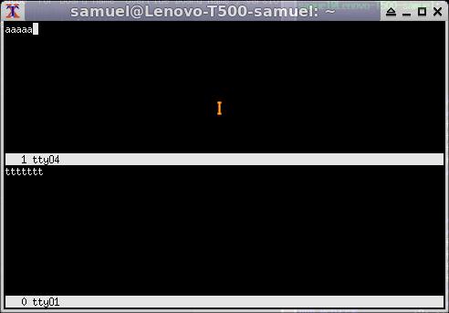
Figure 6. ttyO1 and ttyO4 Screen Session
From now on, you can use the python-serial module to read and write on your serial ports, like this:
import time
from serial import Serial

ctrl_panel = Serial(port=comport, baudrate=9600,
bytesize=8, parity='N', stopbits=1, timeout=0.25 )

# send a commande
ctrl_panel.write(pupitre_commande)

# read an answer
buff = ctrl_panel.read(answer_size)
# as the serial port is configured non-blocking
# with 'timeout=0.25', we make sure all the
# bytes asked for are received.
while len(buff) < answer_size:
  n = len(buff)
  b = ctrl_panel.read(answer_size-n)
  buff += b
  print "------",n,"------"
  time.sleep(0.02)
print "Serial IN: ",
print ' '.join(['%02X' % ord(c) for c in buff])
The python-serial module is quite efficient. We managed to read two serial ports refreshed at 50Hz plus a third at 5Hz (on the same board and simultaneously) with a few glitches between the timestamps, and the CPU load stayed below 50%.
The GPIO:
The General-Purpose Input or Output pins allow the board to receive a signal, read a frequency on input or drive a relay on output.
First we had to understand the mapping between the pin on the P8 and P9 connectors and the GPIO numbers as seen by the kernel. The BBB System Reference Manual gives the Expansion Header P9 pinout (elinux.org/Beagleboard:BeagleBoneBlack#Hardware_Files).
For each GPIO, the name is made up of the GPIO controller number between 0 and 3 and the pin number on the Sitara AM3359AZ. The kernel numbers the GPIO pin with PIN + (GPIO controller number * 32). If we pick the GPIO1_16 on the pin 15 of the P9 connector, the kernel will see it as GPIO_48 (16+(1 * 32)). See Figure 7 to read the direct mapping for all the GPIOs.
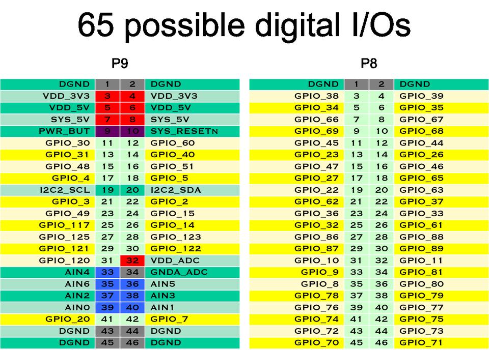
Figure 7. Mapping GPIO Kernel Numbers with P8 and P9 Pinouts
And, you can find a similar table for each kind of I/O port of the BBB on this Cape Expansion Headers page: elinux.org/Beagleboard:Cape_Expansion_Headers
Operate the GPIO:
The gpio_sysfs.txt file, provided with your kernel documentation, explains how to work with GPIOs with a Linux kernel (https://www.kernel.org/doc/Documentation/gpio/sysfs.txt).
These steps are for Linux kernel version 3.8.13. Each GPIO must be enabled independently, so for the GPIO_48 on P9_15:
# echo 48 > /sys/class/gpio/export
Next, choose the way it will operate.
If you want to process input signals:
# echo in > /sys/class/gpio/gpio48/direction
Then choose if you want to detect a “rising” or “falling” edge or “both”:
# echo both > /sys/class/gpio/gpio48/edge
If you want to output signals, you can choose “out” or one of “high” or “low” (telling when the signal is active):
# echo high > /sys/class/gpio/gpio48/direction
And to stop emitting the signal:
# echo 0 > /sys/class/gpio/gpio48/value
At the end, release the GPIO:
# echo 48 > /sys/class/gpio/unexport
Wait for a Signal on a GPIO from Python:
We connected an optical water detector to one of our BBBs inside an enclosure, on the GPIO_48 (P9_15) (Figure 3). The water detector sends a TTL signal if there is water passing through its lens. Here is how we wait for an event describing water presence from Python using the BBB_GPIO class from bbb_gpio.py:
from bbb_gpio import BBB_GPIO

water = BBB_GPIO(48,gpio_edge='both',\
    active_low=True)
for value in water:
    if value:
        print "Water detected !"
    else:
        print "No more water !"
The BBB_GPIO class is a generator. For each iteration, we wait for a change on the GPIO and return in value the GPIO status. When the GPIO is waiting for an event, we don't want to be polling aggressively on the system, but to be awakened only when the event occurs. That's what the poll() system call does. (See bbb_gpio.py line 58—there is a link to my GitHub page with all the code for this article in the Resources section.)
A Special Case, the PPS Signal:
A GPS often delivers a PPS (Pulse Per Second) signal in order to synchronize with good accuracy the timing NMEA sentences, like $GPZDA. The PPS signal is a TTL we can connect to a GPIO; we chose GPIO_49 (P9_23). Once wired, we check whether the signal is present and can be read:
# echo 49 > /sys/class/gpio/export
# echo in > /sys/class/gpio/gpio49/direction
# echo rising /sys/class/gpio/gpio49/edge
# cat /sys/class/gpio/gpio49/value
1
Be careful as to the output voltage of the PPS, as the GPIOs of the BBB accept a TTL of 3.3V max.
The PPS signal is also a special input understood by the Linux kernel. In order to enable our GPIO input as a PPS, we have to compile a dts (Device Tree Source file) into a dtbo (Device Tree Binary Object file) with the dtc (Device Tree Compiler) tool (see the GPS-PPS-P9_23-00A0.dts file on my GitHub page):
# ./dtc -O dtb -o GPS-PPS-P9_23-00A0.dtbo -b 0 \
-@ GPS-PPS-P9_23-00A0.dts
Danger: the dtc program available in Debian Wheezy is not able to write a dynamically loadable dtbo file. It may lack the -@ option, depending on the system you installed. Check the output of dtc -h and whether the -@ is present. (See the Fetching a Good dtc sidebar.)
The dtbo file produced will then be loaded to the kernel:
# cp GPS-PPS-P9_23-00A0.dtbo /lib/firmware
# echo GPS-PPS-P9_23 > /sys/devices/\
bone_capemgr.*/slots
To verify that the PPS is seen correctly by the Linux kernel, you need the pps-tools package installed:
# ppstest /dev/pps0
trying PPS source "/dev/pps0"
found PPS source "/dev/pps0"
ok, found 1 source(s), now start fetching data...
source 0 - assert 1391436014.956450656, sequence:\
 202 - clear  0.000000000, sequence: 0
source 0 - assert 1391436015.956485865, sequence:\
 203 - clear  0.000000000, sequence: 0
source 0 - assert 1391436016.956517240, sequence:\
 204 - clear  0.000000000, sequence: 0
source 0 - assert 1391436017.956552407, sequence:\
 205 - clear  0.000000000, sequence: 0
...
(Ctrl-C to end)
You see here a signal received at 1Hz, with a timestamp jitter less than 1ms.
The i2C Bus:
Two i2c buses on the BBB are available. The kernel sees them as i2c-0 for I2C1 on P9_17(SCL) and P9_18(SDA), and i2c-1 for I2C2 on P9_19(SCL) and P9_20(SDA).
Add an RTC to the BBB:
The DS1307 or the DS3231 are RTC modules with a battery keeping the clock running when there is no power. The ChronoDot RTC (with a ds3231) is much more accurate, and the ds1307 is much less expensive.
Wire the RTC on i2c:
You can feed the 5VDCC of the board to the RTC module as long as you clip out the two 2.2k resistors (Figure 8). The internal resistors of the BBB i2c bus will then be used.
Danger: if you power the BBB over USB, use P9_7 (SYS 5V) instead.
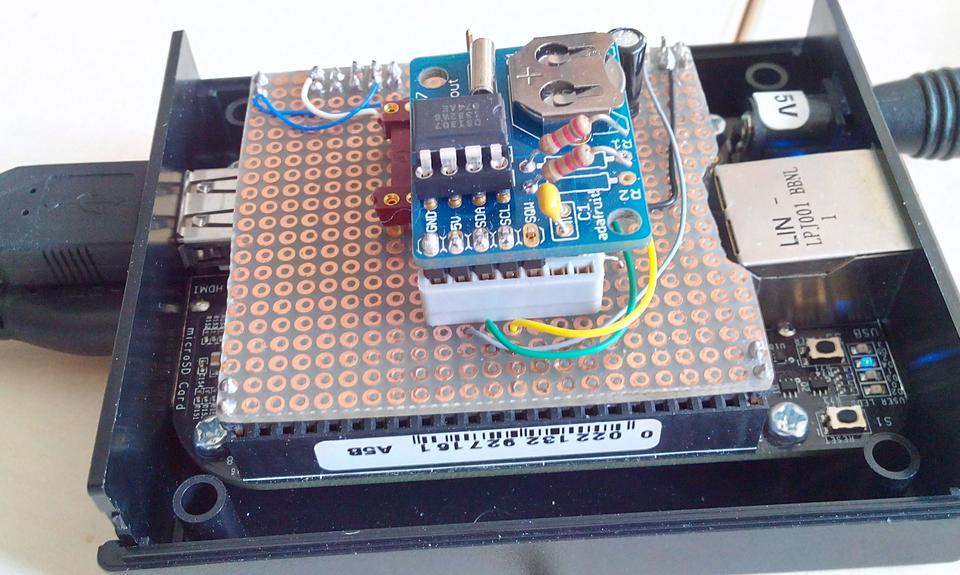
Figure 8. The Adafruit RTC ds1307 Module Wired on the BBB
Enable the New RTC:
Declare the new RTC to the kernel:
# echo ds1307 0x68 >
/sys/class/i2c-adapter/i2c-1/new_device
[   73.993241] rtc-ds1307 1-0068: rtc core: \
registered ds1307 as rtc1
[   74.007187] rtc-ds1307 1-0068: 56 bytes \
nvram
[   74.018913] i2c i2c-1: new_device: \
Instantiated device ds1307 at 0x68
Push the current UTC date to the ds1307:
# hwclock -u -w -f /dev/rtc1
Verify the clock:
# hwclock --debug -r -f /dev/rtc1
hwclock from util-linux 2.20.1
Using /dev interface to clock.
Last drift adjustment done at 1406096765 seconds \
after 1969
Last calibration done at 1406096765 seconds after\
 1969
Hardware clock is on UTC time
Assuming hardware clock is kept in UTC time.
Waiting for clock tick...
...got clock tick
Time read from Hardware Clock: 2014/07/23 15:42:51
Hw clock time : 2014/07/23 15:42:51 = 1406130171 \
seconds since 1969
Wed Jul 23 17:42:51 2014  -0.438131 seconds
To benefit from the new RTC permanently, as soon as the system boots, modify the /etc/init.d/hwclock.sh file with this little dirty hack. Add to the end of the file:
echo ds1307 0x68 > /sys/class/i2c-adapter/i2c-1/\
new_device
HCTOSYS_DEVICE=rtc1
hwclocksh "$@"
Danger: I had to comment the udev part of the file, and I'm still trying to figure how to do that part in a cleaner way:
#if [ -d /run/udev ] || [ -d /dev/.udev ]; then
#     return 0
#fi
If Something Goes Wrong with a Component on i2c:
If the kernel can't see the ds1307, for example, try to detect it on the i2c bus with this:
# i2cdetect -y -r 1
     0  1  2  3  4  5  6  7  8  9  a  b  c  d  e  f
00:          -- -- -- -- -- -- -- -- -- -- -- -- --
10: -- -- -- -- -- -- -- -- -- -- -- -- -- -- -- --
20: -- -- -- -- -- -- -- -- -- -- -- -- -- -- -- --
30: -- -- -- -- -- -- -- -- -- -- -- -- -- -- -- --
40: -- -- -- -- -- -- -- -- -- -- -- -- -- -- -- --
50: -- -- -- -- UU UU UU UU -- -- -- -- -- -- -- --
60: -- -- -- -- -- -- -- -- 68 -- -- -- -- -- -- --
70: -- -- -- -- -- -- -- --
If 68 is not here, but UU is printed, the kernel already keeps hold of the ds1307 with a driver. Recheck your kernel messages and try to unload the driver for the ds1307 with the following, and then retry:
# echo 0x68 >
/sys/class/i2c-adapter/i2c-1/delete_device
# rmmod rtc_ds1307
If this is just -- instead of 68, recheck your wiring.
Add a DAC, the MCP4725, on i2c:
The MCP4725 is a 12-bit digital analog converter, allowing you to output a voltage from a numerical value between 0 and 4095 (212 - 1). Its EEPROM allows you to store a value in a register that becomes the default value as soon as the DAC is powered on. When you want to drive a motor with it, you then can store a default safe value in EEPROM, and then make certain that when the power is restored, your motor doesn't start at full speed.
The wiring is almost identical as for the ds1307 module; take the 3.3V VDD (P9_3) as VREF for the MCP4725.
The MCP4725 address on i2c is 0x60 or 0x61; select it with the A0 pin on the MCP4725. Thus, you can use two MCP4725s on the same bus, so with two i2c buses, you easily can output four independent voltages from your BBB.
Write a Value to the MCP4725:
To set a voltage ouput on the MCP4725, write to the i2c bus. So for a value of 0x0FFF (4095) at the address 0x60 on i2c-1:
$ i2cset -f -y 1 0x60 0x0F 0xFF
Write to the MCP4725 from Python:
The Python module to access the MCP4725 (see the i2c_mcp4725.py file on my GitHub page) is a bit more complex, because we try to handle all the functionalities of the DAC. It depends on the python-smbus package. Here is how we use it:
import time
from smbus import SMBus
from i2c_mcp4725 import MCP4725

dac = MCP4725(SMBus(1), int('0x60', 16))
safe_value = 2047
# write to the DAC and store the value in EEPROM
dac.write_dac_and_eeprom(safevalue, True)

# read the value ouput by the dac and the content
# of its EEPROM
dac.read_and_eeprom()
print dac

# send a mid-ramp 1.69V to 3.38V
for value in range(2048,4096):
  # write to the DAC without storing value
  dac.write_dac_fast(value)
  time.sleep(0.2)
Python subtleties allow us simply to do this:
# send a new value to output a voltage
dac(new_value)
# check the value currently ouput by the DAC
current_value = dac()
How to Read and Verify the Output Voltage?
The BBB has seven analog input ports named AIN{0..6}. They are 12-bit analog digital converters, and they accept a max voltage of 1.8V. To read the voltage from an analog input, wire the GND (P9_1) and the + of the voltage you want to measure.
We re-inject the output of our MCP4725 in AIN0. In this case, the VDD for the MCP4725 is 3.38V (the 3.3V of the PIN 3 and 4 of P9). We divide it by two with two resistors, as it must not be greater than 1.8V. And, we wire the output of the resistors to P9_39 (AIN0).
The vRef for the MCP4725 is VMAX (3.38V), so the voltage we send is:

The vRef for the AIN is always 1.8V, so in order to convert our 12-bit numerical value into a voltage reading, we have:

For a numerical raw value “out”, we must read a numerical raw value “in”, such as:

Read AIN0 from sysfs:
If the BBB ADC kernel driver is not loaded, load it now with:
# echo BB-ADC /sys/devices/bone_capemgr.8/slots
If you need it loaded automatically at boot, do like we did for the BB-UARTs (see the Passing Arguments at Boot Time sidebar).
To read a raw numerical value on AIN0:
$ cat /sys/bus/iio/devices/iio\:device0/\
in_voltage0_raw
3855
$
Is the Input Consistent with the Output?
We can see that the value sent to the MCP4725 is correctly reread on AIN0 (Table 3).
Table 3. Discrepancies between DAC Output and ADC Input
| OUT raw value | IN theoretical raw value | IN read raw value |
|---|---|---|
| 255 | 239 | 243 |
| 2047 | 1927 | 1929 |
| 3839 | 3614 | 3613 |
| 4095 | 3855 | 3835 |
The values match, but there still are some inaccuracies. We need to record a table of corresponding values between the MCP4725 and AIN0 in this configuration. Our control loop driving our propeller's speed can better handle the re-injection of the output voltage.
Read AIN0 from Python:
To read a temperature sensor wired on AIN0 giving 1mV for 0.1°C, we use the BBB_AIN class from the bbb_ain.py file (see my GitHub page):
import time
from bbb_ain import BBB_AIN

tempe = BBB_AIN(0, valeurmax=180)
for value in tempe:
  print "%.4f" % value
  time.sleep(0.5)
Once again, we use a generator. At each iteration, we read a value on the AIN. There is no interrupt mechanism on the AIN; we read at the frequency of the “for loop”—that's why we have to pause at each iteration. The only catch is the error “Resource Temporarily unavailable” (error=11), which may occur occasionally.
How We Use It:
To pilot our propellers, we need to output a voltage between –10 V and 10 V. We use two MCP4725s on i2c_1: one with A0 on V~SS~ (0x60) and the other with A0 on V~DD~ (0x61). We use a bipolar operation type circuit to output –10V/10V from the MCP4725's 0/3.3V output (Figure 9).
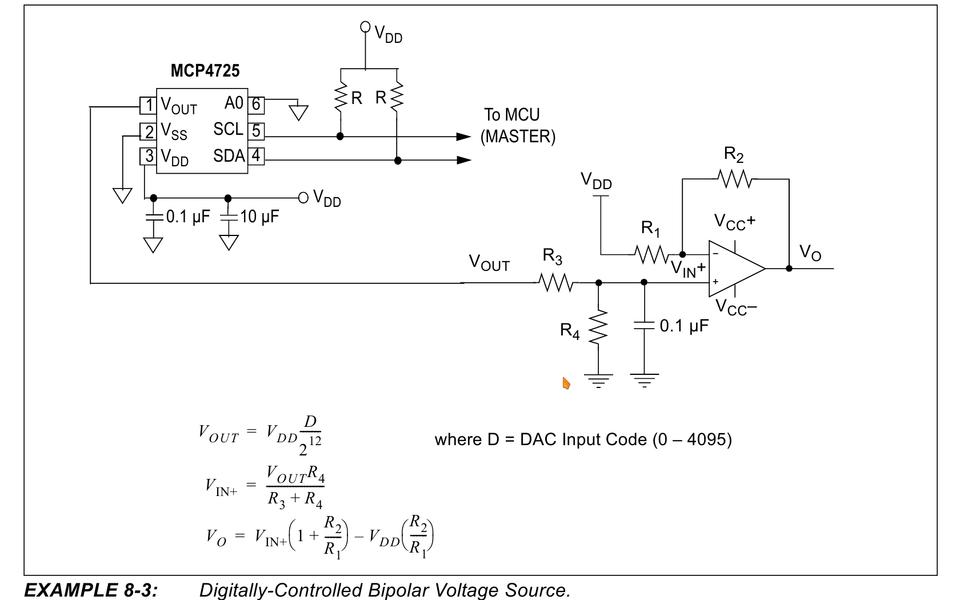
Figure 9. Bipolar Operation Circuit
The MCP4725 outputs are re-injected into AIN0 and AIN1 in order to improve the control loop accuracy. And, we read the speed of the propellers back with two frequency/voltage converters, which we feed to AIN2 and AIN3 (Figure 10).
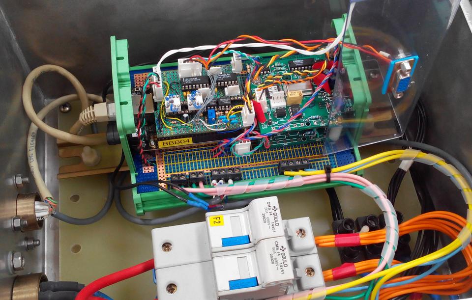
Figure 10. The Box in Charge of the Propellers
The BBB as Time Server from a GPS:
What if you put together the interface to your GPS, the NTP server of your Linux machine equipped with an RTC and the accuracy provided with the PPS signal? You can build an NTP server for other CPUs in your network, and with good accuracy, as soon as the GPS is aligned.
Keep in mind that you need a good RTC wired to the BBB for a real NTP server, so choose one like the Adafruit Chronodot (www.adafruit.com/products/255) rather than the simple DS1307.
GPSd:
Now that you know how to handle a serial port, you can install the GPSd software. GPSd connects to a local GPS, as the one we wired to UART4, and serves GPS data to clients:
# apt-get install gpsd python-gps gpsd-clients
Edit the /etc/default/gpsd.conf file, modify it to connect to your serial port (here ttyO4), and tell GPSd to listen to all network interfaces (-G):
START_DAEMON="true"
GPSD_OPTIONS="-G -n"
DEVICES="/dev/ttyO4"
USBAUTO="false"
GPSD_SOCKET="/var/run/gpsd.sock"
Then restart it:
# /etc/init.d/gpsd stop
# /etc/init.d/gpsd start
By now, your GPS is available to all clients on your network, and you can try to connect to GPSd with QGIS or OpenCPN, for example, but a rather simple solution is with gpsmon. On another machine with the gpsd-clients package installed, launch:
$ gpsmon tcp://bbb02:2947
And, you should see a screen like the one shown in Figure 11.
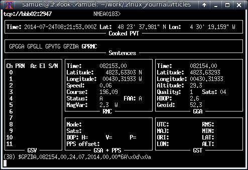
Figure 11. A Session with gpsmon
Connect to GPSd from Python:
The python-gps package provides what you need, but the dialog sequence with GPSd is not trivial. I wrote a little Python class GPSd_client (see the gpsd_client.py file on my GitHub page) in order to be able to access my GPS, like this:
$ ipython
Python 2.7.8 (default, Jul 22 2014, 20:56:07)
Type "copyright", "credits" or "license" for more \
information.
...
In [1]: from gpsd_client import GPSd_client

In [2]: gps = GPSd_client('bbb02')

In [3]: for gpsdata in gps:
    print gpsdata
   ...:
GPS(time=u'2014-07-24T08:53:54.000Z', latitude=\
48.3938485,longitude=-4.505373, altitude=\
30.4, sog=0.051, cog=187.71, ept=0.005, mode=3)
GPS(time=u'2014-07-24T08:53:55.000Z', latitude=\
48.393848, longitude=-4.505373167, altitude=\
30.3, sog=0.067, cog=194.8, ept=0.005, mode=3)
GPS(time=u'2014-07-24T08:53:56.000Z', latitude=\
48.393847667, longitude=-4.505373167, altitude=\
30.2, sog=0.062, cog=184.8, ept=0.005, mode=3)
GPS(time=u'2014-07-24T08:53:57.000Z', latitude=\
48.393847333, longitude=-4.505373167, altitude=\
30.2, sog=0.036, cog=189.77, ept=0.005, mode=3)
GPS(time=u'2014-07-24T08:53:58.000Z', latitude=\
48.393847167, longitude=-4.505373, altitude=\
30.1, sog=0.041, cog=175.46, ept=0.005, mode=3)
^C---------------------------------------------\
------------------------------
Again, we use a generator. For each iteration, the GPSd_client class opens a session with GPSd, listens for a report with position and time information, closes the session and returns a namedtuple with the information we wanted.
NTPd:
One of these GPSd clients is NTP. NTPd processes the NMEA GPS timing sentences to set the date and uses the PPS signal to be more accurate. The handling of the PPS signal is available only in the development versions of NTPd, not the version in the Debian repositories. The version we installed is ntp-dev-4.2.7p416. Grab it and compile it like this:
# apt-get install libcap-dev
# wget http://www.eecis.udel.edu/~ntp/ntp_spool/\
ntp4/ntp-dev/ntp-dev-4.2.7p416.tar.gz
# tar xf ntp-dev-4.2.7p416.tar.gz
# cd ntp-dev-4.2.7p416/
# ./configure --enable-all-clocks --enable-\
linuxcaps
# make
Modify the /etc/ntp.conf file for the connection to GPSd and the PPS signal listening:
# Server from shared memory provided by gpsd
server 127.127.28.0 prefer
fudge 127.127.28.0 time1 0.040 refid GPS

# Kernel-mode PPS ref-clock for the precise seconds
server 127.127.22.0
fudge 127.127.22.0  flag2 0 flag3 1  refid PPS

# allow ntpd to serve time if GPS is OFF
tos orphan 5
The 0.040 might need adjusting relative to your GPS, but it's a safe bet. The 127.127.22.0 is the NTPd reference to /dev/pps0. If your GPSd declares a /dev/pps to the kernel, your real PPS signal might become /dev/pps1. The bottom line is try to load your PPS signal before starting GPSd.
Verify that NTPd has started and serves the time with ntpq:
# ntpq -p
     remote           refid      st t when poll \
     reach   delay   offset  jitter
================================================\
==============================
*SHM(0)          .GPS.            0 l   13   64 \
  377    0.000  -50.870   0.886
oPPS(0)          .PPS.            0 l   12   64 \
  377    0.000   -1.419   0.128
You can see here that .GPS. is identified as the system peer by ntpd (*), and .PPS. is also correctly recognized and valid (o).
The two Programmable Realtime Units of the BBB can work independently of the main CPU on I/O ports, AINs and PWM. They are sophisticated enough to share memory with a CPU up to 300MB, have a rich instruction set and can trigger or receive interrupts.
Recently, some hard workers managed to make the use of the BBB PRUs more accessible. And, there is this great promising GSOC 2014 coming, BeagleLogic: https://github.com/abhishek-kakkar/BeagleLogic/wiki.
See also the work of Fabien Le Mentec: “Using the BeagleBone PRU to achieve real time at low cost” (www.embeddedrelated.com/showarticle/586.php).
The BeagleBone Black is a very fun platform to play with. As a Linux sysadmin for nearly 20 years, I'm very comfortable using it to access electronic hardware I'm not so well acquainted with usually.
I want to thank my co-worker, Rodolphe Pellaë, whose skills in electronics were essential in connecting all the components to the board. He did our four homemade Capes in no time and did them well.
The community orbiting the BBB is large with a lot of good on-line resources. We managed to learn some complex stuff in very little time and with almost no confusion, because we can profit from the work of those people and from the Linux and Python ecosystems.
