
Build your own ATmega328p programmer with the BeagleBone Black. This tutorial starts from raw components and shows you how to assemble the hardware, manipulate the kernel's device tree files and write the software for a complete soup-to-nuts project.
The Raspberry Pi is the inexpensive, embedded Linux computer that comes to mind for most Linux Journal readers. Last year, the Pi swept three Readers' Choice Awards: Linux Product of the Year, Best Other Linux-Based Gadget and Best New Open-Source Project. However, I was in the proud 3.3% of readers who voted for the BeagleBone. Although the Pi may have the popularity, the BeagleBone Black (BBB) has a faster processor, 2GB of onboard eMMC storage and more than 65 different Input/Output (I/O) pins. These features make the BBB my embedded development platform of choice. However, for some truly low-level projects, it is more appropriate to use an embedded microprocessor, such as that provided by the familiar Arduino platform.
In this project, I describe how to combine the ATmega328p, the microprocessor on the Arduino UNO, with the BBB. Specifically, I detail the steps needed to use the BBB as a programmer for the ATmega328p so that you can upload sketches built with the Arduino IDE directly to the chip!
There are a few open-hardware projects that incorporate this technique. For example, one of the most successful BBB projects, OpenROV, uses a similar configuration. OpenROV is an open-source (software and hardware) underwater exploration robot. On the robot, the ATmega328p controls the servos for movement. There is another BBB cape that uses an ATmega328p: the CryptoCape. The CryptoCape is a collaborative project between SparkFun Electronics and Cryptotronix, my open-hardware company. The cape also contains various other security Integrated Circuits (ICs), like a Trusted Platform Module (TPM), an encrypted Electrically Erasable Programmable Read-Only Memory (EEPROM), a Real-Time Clock with an attached holder for a coin-cell battery and ICs that perform the Elliptic Curve Digital Signal Algorithm (ECDSA). I've included an ATmega328p on the CryptoCape for users to upload their own crypto-library to the microcontroller or to use the microcontroller to interface with other hardware.
The soon-to-be-released Arduino TRE combines the Atmel ATmega32u4 with the Texas Instrument Sitara ARM Cortex-A8. The Arduino TRE is a collaborative effort between BeagleBoard.org and Arduino, and early looks indicate that it has four USB ports, HDMI, audio In/Out, Ethernet and power options for a 5V jack and USB power. Until the TRE is available, you can make your own BBB and ATmega cross-breed using the approach outlined here.
In this configuration, think of the BBB as a front end for the ATmega328p. Imagine a configuration where the ATmega328p is controlling an electromechanical device, but the firmware needs to be updated. With an attached BBB, the BBB can run a Web server, accept the new firmware and update the ATmega328p without a programming cable.
For completeness, there is another option for those looking for a low-level hardware interface on the BBB. The BBB contains two independent Programmable Real-Time Units (PRUs). The two PRUs on the BBB run at 200MHz and have shared memory with the main processor. The PRUs run at much higher speeds than AVRs and are better suited for high-speed applications like real-time motor control or video encoding/decoding. Although there is an example library provided by BeagleBoard.org, the PRUs are more complicated and have a slightly higher learning curve. The software support is not as mature as the Arduino project, and for custom applications, one needs to program in assembly for the PRU instruction set. However, if execution speed is critical for your application, it may be worth your time to learn about the PRU.
When combining the ATmega328p and the BBB, you must consider the operating voltages of both devices. The Arduino UNO, which is built around the Atmel ATmega328p, operates at 5V, while the expansion headers on the BBB operate at 3.3V. To combine the BBB and the ATmega328p, you must decide whether to operate all components at 3.3V or use logic-level converters and supply power to the ATmega328p at 5V. If operating at 3.3V, you also must reduce the crystal frequency for the ATmega328p from 16MHz to 8MHz. For this tutorial, I've chosen to keep all voltages at 3.3V, because the circuitry is simpler, and I can afford the reduced processor speed.
This tutorial has three parts. First, I describe the hardware components and skills required to build the prototype. Second, I detail the software required to power, program and communicate with the microprocessor. And finally, I show how to upload sketches onto the ATmega328p.
This project does require soldering. However, I have chosen to use only through-hole components, which generally are easier to solder. If you are new to soldering, the SparkFun Web site has some great tutorials (see Resources).
For this project, you need the following components:
Soldering equipment (iron, solder).
(1) ATmega328p in DIP package.
(2) 22 pF capacitors (for the crystal).
(2) .1 uF capacitors (for decoupling).
(1) 8MHz crystal.
Hookup wire.
(1) 6-pin shrouded connector.
(1) Protoboard.
Male breakaway 0.1 inch pins.
AVR Programmer (AVR Pocket Programmer).
(Optional) AVR breakout board.
(1) LED.
I've made a public SparkFun wish list that lists all of these components (see Resources).
There are two ways to build the hardware for this project: the easy way is to use a solderless breadboard to assemble the components, and the harder way is to build a prototype cape. I generally try to get projects working on a solderless breadboard first, before I start soldering components onto a protoboard, but sometimes a breadboard introduces challenges with poor connections. Refer to the Fritzing diagram for details of the breadboard implementation (Figure 1).
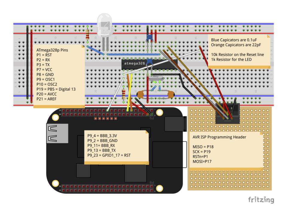
Figure 1. Schematic for the ATmega328p-BeagleBone Combination
If your ATmega328p already has a bootloader, you can skip the ISP programming header, but it's very handy to flash a bootloader quickly or sketch on the microprocessor if there is a problem. However, you should not connect the ISP programmer to the board while connected to the BeagleBone. The programmer is most likely using 5V, and the VCC line is tied to the main power supply from the BBB, which is 3.3V. You could add logic-level converters to make this safer, but it adds some complexity.
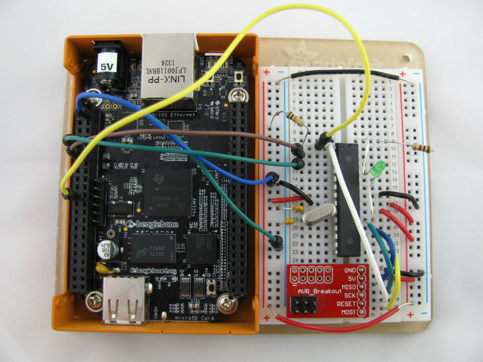
Figure 2. BBB with an ATmega328p on a Solderless Breadboard (photo by Josh Datko)
The benefit of using a protoboard is that you will have a much more stable prototype, both electrically and mechanically. However, it requires more of a time investment and significantly more soldering. The protoboard also requires some 0.1" male headers to attach into the BBB's expansion headers. You could get away with soldering just the pins that are used in this project, but I recommend attaching the entire 2x23 male headers.
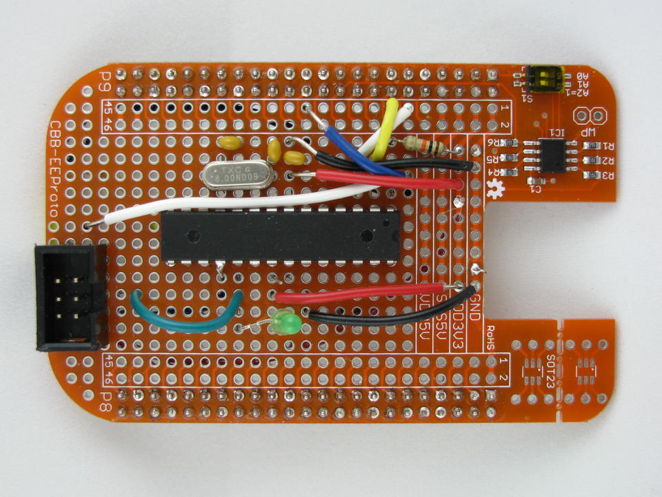
Figure 3. ATmega328p on the Logic Supply BeagleBone Proto Cape with EEPROM—Front (photo by Josh Datko)
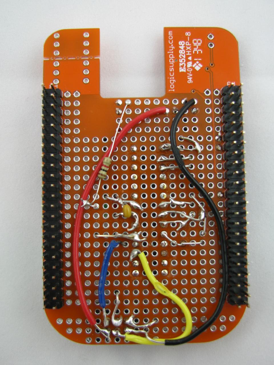
Figure 4. ATmega328p on the Logic Supply BeagleBone Proto Cape with EEPROM—Back (photo by Josh Datko)
Flashing a Bootloader
There are several ways to load a bootloader, including purchasing an ATmega328p with a pre-installed bootloader. The method I chose was to use the Arduino IDE and the AVR Pocket Programmer. To load the bootloader, connect the six-pin ISP cable to your ISP header and the USB end to your host computer. Select “Power Target” on the Pocket Programmer. In the Arduino IDE, select a board type of “Arduino Pro or Pro Mini (3.3V, 8MHz) w/ ATmega328”. Under Programmer, select “USBtinyISP”. Then select “Burn Bootloader”. After a few minutes, you should be rewarded with the message “Done burning Bootloader”. With a bootloader installed, disconnect the programmer and attach the cape to the BBB.
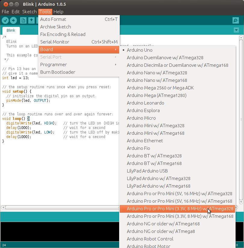
Figure 5. Select Arduino Pro or Pro Mini (3.3V, 8MHz) with ATmega328.

Figure 6. Select USBtinyISP.
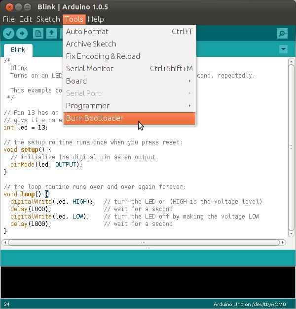
Figure 7. Finally, select Burn Bootloader.
Preparing the BBB
There are three wires required for the software reset and sketch upload feature. Two are for serial Transistor-Transistor Logic (TTL) data transmit (TX) and receive (RX), and the third line is a General Purpose Input Output (GPIO) pin, used to toggle the reset line. You can manipulate the pins through the exported sysfs, but first you must determine the pins to use. For the reset line, arbitrarily pick a GPIO pin. For this example, pick pin P9_23, which is GPIO1_17. The BBB System Reference Manual (SRM) contains the mapping of pins to pin mode in Table 13 for the P9 Header.
Let's further break down the GPIO number. The 1 in GPIO1_17 refers to the GPIO controller. There are four GPIO controllers on the BBB, numbered 0 through 3. The second number, 17, is the pin ID on that GPIO controller. The interface to the Linux kernel's GPIO driver requires you to use a single GPIO number. Therefore, you need to understand the mapping from the BBB's SRM GPIO naming convention to the kernel. To help understand, mount the debugfs, if it's not already mounted with:
mount -t debugfs none /sys/kernel/debug
Then, view the GPIO information with:
cat /sys/kernel/debug/gpio
The result should be something like this:
GPIOs 0-31, gpio:
 gpio-6   (mmc_cd              ) in  hi

GPIOs 32-63, gpio:
 gpio-49  (sysfs               ) out hi
 gpio-52  (eMMC_RSTn           ) out lo
 gpio-53  (beaglebone:green:usr) out hi
 gpio-54  (beaglebone:green:usr) out lo
 gpio-55  (beaglebone:green:usr) out hi
 gpio-56  (beaglebone:green:usr) out lo
 gpio-59  (McASP Clock Enable P) out hi

GPIOs 64-95, gpio:

GPIOs 96-127, gpio:
Here you see the four GPIO controllers on the BBB. The GPIO you want to use is GPIO1_17, which you now know is on GPIO controller 1. You also now know the offset. GPIO0 controls 32 GPIOs, 0–31. GPIO1 also controls 32 GPIOs, 32–63. You want the 17th GPIO on GPIO controller 1, which starts at 32; therefore, the number you need is 32 + 17 = 49.
Now that you know the mapped pin number, you can control the pins from userspace with basic shell scripting. It's a three-step process. First, export the desired pin. Then, set the direction of the pin for either input or output. Finally, set the pin to a logic high (“1”) or low (“0”).
Export the pin with the following command, as root:
echo 49 > /sys/class/gpio/export
With the pin now exported, set the direction and value with the following two commands:
echo out > /sys/class/gpio/gpio49/direction
echo 1 > /sys/class/gpio/gpio49/value
The first command declares the pin as an output, and the second command sets the reset line high and powers the ATmega328p. Now your reset line is ready to go.
It is a bit trickier to enable the TTL serial lines. Per the BBB SRM, I've chosen UART4 TX and RX, which maps to P9_13 and P9_11. However, because these are going to be used in a different mode, namely serial TTL, the pins cannot be mapped like normal GPIOs. In this case, for the 3.8 kernel series on the BBB, it's easiest to build a device tree fragment and load it at runtime with the BeagleBone's Cape Manager (Capemgr).
The BBB uses the Linux kernel's device tree system, but the Capemgr is a BBB-specific solution. For complete BBB capes, during system startup, the kernel will probe the four authorized EEPROM addresses and try to match the cape name and version, stored in the EEPROM, with compiled device tree files. But, it's also possible to load a compiled device tree object at runtime from userspace.
The following snippet shows the key insight to configuring the device tree on the BBB; it is based on the fragments for the BeagleBone Black in am335x-bone-common.dsti (the complete code is in my GitHub repository listed in the Resources section):
fragment@0 {
    target = <&am33xx_pinmux>;
    __overlay__ {
        pinctrl_uart5: pinctrl_uart5_pins {
            pinctrl-single,pins = <
                0x070 0x26  /* P9_11 = MODE6 */
                0x074 0x06  /* P9_13 = MODE6 */
            >;
        };
    };
};
The “magic” numbers contained in the pinctrl-single,pins property warrant some explanation. This device tree snippet is changing the mode of the pins with the kernel's Pin Control subsystem. Specifically, the driver is the pinctrl-single driver. The documentation for that driver states that the first 32-bit value in the two 32-bit value pair (known as “cells” in the device tree documentation) is a register offset whose value to be set is the second 32-bit value. The source document that describes the registers is the ARM Cortex-A8 AM335x's Technical Reference Manual. This is the manual for the processor on the BBB. The second value is a hex encoding for the mode and control for that pin. The least significant six bits of this value are encoded per Table 1.
Table 1. Bit Encoding
| Bit | 0 | 1 |
|---|---|---|
| 6 - Slew Control | Fast | Slow |
| 5 - Receiver Active | Disabled | Enabled |
| 4 - Pullup or Pulldown | Pulldown | Pullup |
| 3 - Enable Pulls | Enabled | Disabled |
| 2,1,0 - Mux Mode | Mode 0 through 7 |
In this example, P9_11 is decoded as follows: fast slew control, receiver active, internal pulldowns are disabled, and mode 6. In the BBB System Reference Manual, mode 6 for this pin corresponds to UART4_RXD, which is exactly what you want.
With the device tree source in hand, compile the file with the device tree compiler (dtc), copy it to the /lib/firmware directory and enable the overlay.
dtc -O dtb -o enable-uart5-00A0.dtbo -b 0 -@ enable-uart5.dts

cp enable-uart5-00A0.dtbo /lib/firmware/
echo enable-uart5 > /sys/devices/bone_capemgr.*/slots
If dtc complains about the @ symbol, update dtc with the following script:
wget -c https://raw.github.com/RobertCNelson/tools/master/pkgs/dtc.sh
chmod +x dtc.sh
./dtc.sh
This will download a patched version of the dtc that supports this feature.
Run dmesg|tail to verify that the device tree was loaded successfully, and you should see messages similar to this:
bone-capemgr bone_capemgr.8: slot #8: Requesting
    part number/version based 'enable-uart5-00A0.dtbo
bone-capemgr bone_capemgr.8: slot #8: Requesting
    firmware 'enable-uart5-00A0.dtbo' for board-name
    'Override Board Name', version '00A0'
bone-capemgr bone_capemgr.8: slot #8: dtbo
    'enable-uart5-00A0.dtbo' loaded;
    converting to live tree
bone-capemgr bone_capemgr.8: slot #8: #3 overlays
481a8000.serial: ttyO4 at MMIO 0x481a8000
    (irq = 61) is a OMAP UART4
The last line tells you that the serial device, /dev/ttyO4, is now ready.
With the hardware in place and the interfaces ready, there are two pieces remaining. You need a mechanism to transmit sketches from the host computer to the BBB, and then you need a mechanism to upload the sketch to the ATmega328p. The first piece can be solved in numerous ways. I wrote a simple Python Web server that receives sketches via a POST and then launches the script to flash the ATmega328p. There are lots of examples of how to do this in Python, so I'll leave this as an exercise for the reader. Although, you can take a look at server.py in my GitHub repo for this tutorial listed in the Resources section for an example.
The Arduino IDE compiles and uploads sketches directly from the GUI. You still can use the IDE to compile sketches, but your BBB programmer isn't supported. In the Arduino preferences, select verbose output for compilation. When you compile your sketch, the output window will show the location of your compiled file which should be something like: Blink.cpp.hex.
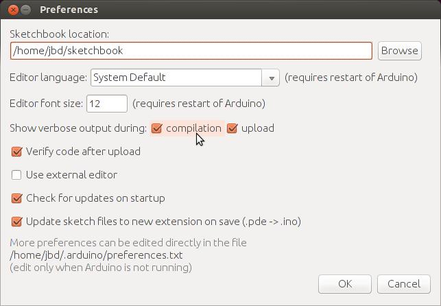
Figure 8. Selecting verbose compilation is helpful in finding the compiled sketch.
The script to upload the sketch to the ATmega328p is a bit trickier. Before proceeding, install the avrdude package on the BBB. Avrdude is the “AVR Downloader/UplodDEr” and is the back-end utility that the Arduino IDE uses to upload sketches. Avrdude alone should be sufficient, but if you want the full tools on your BBB, install the following extra packages:
gcc-avr
binutils-avr
gdb-avr avr-lib
This script works on the principle that the ATmega328p bootloader will monitor the serial TTL lines shortly after a reset for incoming programs. Therefore, you must coordinate the reset of the ATmega328p with the start of the transmission. Use the following bash snippet to upload the sketch:
#!/bin/bash
if [ "$#" -lt 1 ]
then
  echo "Usage: $0 sketch.cpp.hex [time to sleep]"
  exit 1
fi

pin=49
serial=/dev/ttyO4

if [ "$2" == "" ]; then
   tts=.9
else
   tts=$2
fi

echo Waiting $tts seconds

(echo 0 > /sys/class/gpio/gpio$pin/value \
    && sleep $tts \
    && echo 1 > \
    /sys/class/gpio/gpio$pin/value) &

avrdude -c arduino -p m328p -b 57600 -v \
    -P $serial -U flash:w:$1
The first command splits off a subshell that will toggle the reset line. After a brief delay, the avrdude command flashes the sketch. Use the -c option to indicate the arduino programmer, which is the closest setup to this hardware. Since the processor is running at 8MHz vs. 16MHz, cut the serial baud rate in half (-b 57600).
You may need to adjust the timing values. A logic analyzer is very helpful in this situation to see the logic levels; otherwise, you are left to trial and error. If you intend to dive deeper into hardware, a logic analyzer is well worth your investment.
The text should scroll by and you should see output similar to this:
avrdude: reading input file "sketch.hex"
avrdude: input file sketch.hex auto detected as
         Intel Hex
avrdude: writing flash (1084 bytes):

Writing | ######################## | 100% 0.30s
If you've uploaded the standard Arduino Blink sketch, the LED on your cape should be blinking! Congratulations, you've just programmed the ATmega328p from your BeagleBone Black!
This project showed the minimal configuration needed to program an ATmega328p from a BBB. Serial TTL is just one way to communicate with the ATmega329p, however. Many devices can be connected on the I2C bus, including the ATmega328p. What's nice about I2C on the BBB is I2C is enabled by default on pins P9_19 and P9_20. There are no extra device tree overlays or steps required to configure this. Also, both the BBB and the ATmega328p can communicate over the Serial Peripheral Interface (SPI) bus.
Be warned, hardware hacking is addictive! The first time you build a semi-complicated circuit and watch the LED blink in front of you, it's like the first time you booted into your modified kernel. Have fun and Happy Hacking!
