
How to use a standard Linux distribution platform to make a user interface embedded into a vehicle monitoring and control system.
The target vehicle for this project is a vintage intercity transport bus (think Greyhound) whose instrument panel was sparse and mostly nonfunctional. The speedometer cable was twisted off some place back in 40 feet of cable, and the fuel sensor had sunk long ago. What I wanted was an instrument panel more in line with modern practice.
To bridge the gap, I used a laptop computer running the Fedora 20-KDE distribution of Linux as a host, three digital signal processor boards as hardware interface processors (HIPs), a USB/RS422 converter that connects to an RS422 loop linking the HIPs together and some software that I call the Vehicle Monitoring and Control application.
The HIPs are based on a signal processor chip, programmed in C and with no user interface except a heartbeat LED to show that the processor is working to some degree. The HIPs provide signal conditioning circuitry for analog input scaling and optical isolation for control signals plus a few specials like thermocouple converters and a pressure transducer chip. There also are two RS422 receiver/transmitter pairs. One pair connects up-network (toward the host) and the other down-network (toward the other HIPs).
The way this application works is that a message is originated by the host processor and transmitted down-loop to the first HIP. There it may be modified under HIP program control and relayed on down-loop to the next HIP. The last HIP in the “loop” transmits its message up-loop under physical jumper control. Processors closer to the Host simply pass on up what is coming from below in the “loop”. The Host is the ultimate receiver of the messages it originates.
A message consists of an SOM byte, an address byte with acknowledge bit, a command byte, four data bytes and two CRC bytes. Going down loop, the HIPs relay a message on a character-by-character basis with a one-character delay per HIP. The addressee of a message sets the acknowledge bit and inserts or extracts data on the fly. So in a short loop like the one here, the host begins receiving the response from the network before it has finished sending the original message. For this loop, the communication rate was selected, arbitrarily, as 57,600 baud, so the loop message time is (9 + 3)/57600 or 208 microseconds. The left portion of Figure 1 depicts the loop topology.
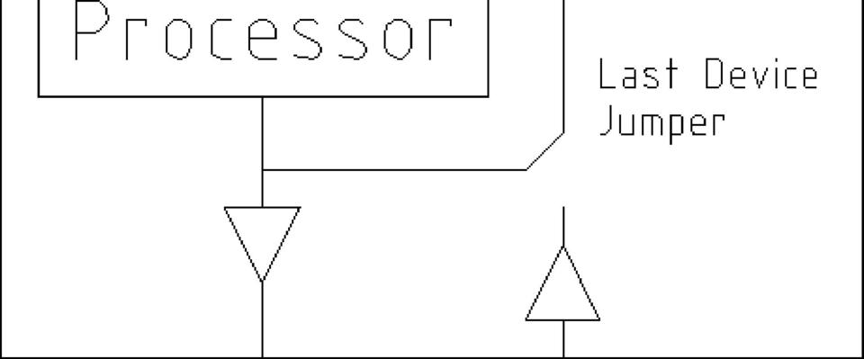
Figure 1. System Architecture
The Vehicle Monitoring and Control (VMC) application will originate messages like “HIP1 set or get register whatever”. First, I show how to set up a development environment on a Linux box, and then I talk about how to use the tools made available there to weave together a Linux real-time application that performs the VMC application.
My choice for a development environment is KDevelop from KDE, and for a toolkit, it is Qt from the Qt Project. The first step is to get the development environment and then build a “Hello World” application. So, here it is in the Fedora world:
yum install kdevelop
yum install qt
yum install gcc
...and lots of other stuff. Expect to spend some time if you are not already up and running with Qt.
When you get KDevelop to load, click Session→Start New Session→New Project. This will be “Qt” and “Graphical”. Make up a name (VMC for example), accept the defaults, and soon you will be presented the opportunity to “Build” and then “Execute”. On “Execute”, a Launch Configurations dialog box will enable you to select your project name, “Add New”, and your project. A click or two later, and you should see a basic “Hello World” window appear on your screen. This you may expand into your real-time application.
The “Hello World” you see is a Qt application. Qt is an excellent toolkit that is robust and well documented—except for a few quirks. The new project build process creates a directory structure that includes ~/projects/VMC/build. To minimize hard-to-diagnose Qt build errors, keep all of your source and header files in ~/projects/VMC until you know how to do otherwise. The ~/projects/VMC/build directory is the execute directory for the purposes of KDevelop. It is here that run directory files should reside. As you add source files and libraries, you must keep ~/projects/VMC/CmakeLists.txt current.
Here is how to use tools available in the Linux environment to create the VMC application. First up is communications. To your application, the communication loop looks like a file stream created like this:
int hNet = open("/dev/ttyUSB0", O_RDWR);
or /dev/ttyUSBwhatever, depending upon what else is going on in your system.
Now you can read() and write() hNet and the USB<->RS422 converter will connect you to the loop. Writing is no issue up to loop speed (in this case 57600/9 = 6400 messages/second), so that is your write (hNet,...) speed limit. Reading is a different deal as read(hNet,...) is a blocking operation. A process that makes that call remains stuck there until some data arrives. Thus, you want to make your read(hNet,...) calls from a process (thread) whose only task is to catch characters as they come in and then make them available in a buffer to other processes as they need them—most briefly, in abbreviated code:
//A thread to perform the read(hNet,...) function
class COMthread : public Qthread
{
Q_OBJECT    //Notice use of the Qt tools
protected:
     //Start point when myThread->start(); is called
void run()
{
while (1)
{
pthread_mutex_t mutex1\
         = PTHREAD_MUTEX_INITIALIZER;
//Lock out other processes while working
pthread_mutex_lock( &mutex1 );
          -manipulate shared variables here-
//unlock for other processes during read(hNet,...
pthread_mutex_unlock( &mutex1 );

//This is where this thread spends
read(hNet, Buf, BUF_SIZE);/////////
//99.99 (+/-) percent of its time

//Now lock while updating for new data
pthread_mutex_lock( &mutex1 );
         -buffer data and update pointers-
pthread_mutex_unlock( &mutex1 );
}
}
};
To activate that code, your statements in the VMC constructor are:
COMthread   *gCOMgo = new COMthread;
gCOMgo->start();
The complement to that loop data fetch is a character fetch routine running under some other process. That routine, using its own mutexes, extracts data from the buffer sourced by the thread above.
Now that you can send and receive data via the loop, let's look at how the application may interact with the hardware.
Figure 2 shows the Instrument Panel display as seen on a video display mounted in the driver's view.
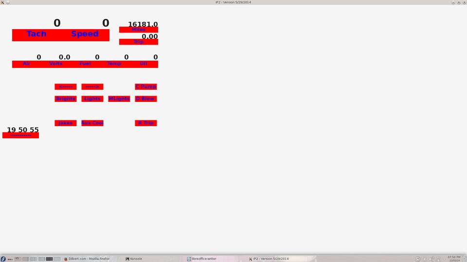
Figure 2. Instrument Panel Display
The Tach and Speed display data are sourced from timer registers in an HIP that is timing the period between shaft rotations. The five indicators below are sourced by A/D registers in various HIPs. These seven data items are collected by sending seven nine-character data request messages to the loop and decoding the returned 63 characters (7X9). Below that is a representation of a partially populated map of a 4X4 keypad that is serviced by one of the HIPs. Each of the represented keys on that map issues a query for the HIP responsible for the physical keypad to see if its key was the last pressed. It gets back yes or no.
When you use KDevelop to create a VMC project, some files of interest to you now were created. Look in directory ~/projects/VMC, and there you will find main.cpp and VMC.cpp. File main.cpp is fine as is. It simply declares and runs the application described by the code in VMC.cpp. None of the sample code in VMC.cpp within the curly braces is useful for you, so let's replace it with the constructor for the VMC application. As I mentioned previously, this application relies upon Qt, so an important resource for you is qt-project.org/doc/qt-4.8/classes.html.
Your VMC class will inherit from QmainWindow, so your constructor will be defined in VMC.cpp as shown here:
 VMC::VMC() : QMainWindow()
 {
 //declare a central widget to host our screen:
 QWidget* gCentralWidget = new QWidget(this);
 setCentralWidget(gCentralWidget);
//Set fonts, colors, geometry, etc
       - - - -
//Declare an object to hold the screen features:
ScreenC cScreenLayout = new ScreenC();
//Lastly, breathe life into the application
cHeartBeat = new QTimer (this);
connect(cHeartBeat, SIGNAL(timeout()), this,\
                          SLOT(slotPaintScreen()));
cHeartBeat->setSingleShot(false);
cHeartBeat->start(50); //milliseconds/20Hz
}
That is an abridged view of the constructor, but the actual code isn't much longer. The connected routine slotPaintScreen() will be activated on a 50 millisecond interval by the timer overflow. It too is brief:
//Fetch loop characters gathered by COMthread
SensorLoopService();
//Update the display
cScreenLayout->Update();
//Redraw the screen
update();
(Again abridged because this is a story about how to do it rather than how to code it.)
The central portion of Figure 1 shows the cascade of object creation that will embody the VMC application. Notice the declaration of a ScreenC object by the VMC constructor and the update of that object at a 20Hz rate.
The ScreenC class constructor simply declares a ScreenItemC object for each entity that appears on the screen. A typical declaration is:
pF[i] = new ScreenItemC(xOff,yOff,xSiz,ySiz,\
                  MEAS_TACHOMETER, 0, "Tach");
Here you define the location and size and name the object type of each on-screen object. At update time “update” is simply relayed to its children like this:
//Update screen features
for (i=0; i<cNumberFeatures; i++)
{
 pF[i]->Update();
}
The ScreenItemC class constructor is responsible for the look of items on the screen. In this application, a ScreenItemC item consists of two QLabel objects placed one above the other so as to appear to be a single instrument. The form of a QLabel declaration is:
QLabel cReading = new QLabel(gCentralWidget, Qt::FramelessWindowHint);
The instrument displays of Figure 2 are pretty “plain Jane”. It is here in the ScreenItemC class code where you can fancy it up. The ScreenItemC constructor also declares a MeasureC object. That object's update routine returns the data that the ScreenItemC object places on the screen:
MeasureC cMeasure = new MeasureC(MEAS_TACHOMETER);
The MeasureC class is where the hardware interface is described. HIP address, register numbers and scale factors are defined. For example:
case MEAS_TACHOMETER:
{
fScale = 27648000.0;  //29.75Hz -> 1788rpm
      // RPM = fScale / binary from loop + fOffset
fOffset = 0;
rule = MEAS_RULE_RECIPROCAL_TACHO;
DeviceId = NODE_E;                  //Loop device id
DevicePort = P_IC_PERIOD_2;  //Sensor on device
//Create a sensor for the measurement
pSens = new SensorC(MEAS_TACHOMETER,\
    DeviceId, DevicePort, fScale, Offset, rule);
break;
}
Notice the declaration above of a SensorC object. At update time, that SensorC object will fetch its most recent raw reading from the loop buffer, scale that and return the result to its MeasureC parent, which will relay that back to its ScreenItemC parent, which will display that result on the screen. The MeasureC items that represent a keypad key will declare a ContrtolC object here. The ControlC object will use its own SensorC object to inquire of the loop if its key is the most recently pressed. ControlC objects also run device-specific code (like timing a blinker, for example). The ControlC object may place commands on the loop as necessary. The ControlC update routine will return 1 or 0 depending on whether its control target has changed state or not. That return flows back up the cascade to its grandparent ScreenItemC object and then is reflected on the display.
This cascade of object creation ends with SensorC objects that return the result of their previous request to the loop and issue a new data request at each update time. As ControlC objects may place commands on the loop at their whim, the loop will have a mixture of independent commands circulating that must be resolved back to their originator. When a command is issued to the loop, the issuer of that command also inserts into a class visible circular buffer a pointer to itself.
As mentioned above, slotPaintScreen() will call SensorLoopService() at each update time. SensorLoopService() extracts characters that have been placed into the loop receive buffer by the gCOMgo thread. Mutexes are used here to prevent interference by other threads. SensorLoopService() parses the characters as it fetches data from the buffer, and when it has detected a complete valid message, it places the four data bytes into a location pointed to by the pointer mentioned above. This data will be returned up the cascade at the next update time.
Here it is in fewer words: the update event cascades down from the ScreenC object to multiple SensorC objects that bounce parameter states back up to ScreenItemC objects that paint those states on the screen. The left panel of Figure 1 depicts this.
Some kinks that Linux throws in include the screen saver that defaults active, but is bad news in a monitoring application. To turn it off, go to System Settings→Power Management and disable all Screen Energy Saving options. Another issue is automatic software updates. It is my consideration that if something works, don't screw around with the operating environment, as software updates do. The safest way to suppress updating is by staying off the Internet while your application is active. Another way is to disable updates by software control. To do so, go to the Application Launcher (lower left on the desktop), and start the System Settings from Favorites, go to Software Management and left-click the wrench icon at the upper-right edge. Select Settings from its menu. In the General Settings page, set the Check for updates menu to Never, and “Apply” that. Also, go to /etc/yum/pluginconf.d/refresh-packagekit.conf and set enabled to 0 (disable update). For me it was just too easy to switch off the Wi-Fi when I wanted a stable environment, so I can't give you other advice here.
To claim credit as being an “embedded” application, this system should come up with the power—that is, without login or any other user input required to make it go. To kill the login, go to /etc/kde/kdm/kdmrc and set AutoLoginAgain=true and AutoLoginUser=YourUserName. To bring up your application with system start up, go to ~/.kde/Autostart and place an executable script there like this:
#!/bin/bash
cd /home/YourUserName/projects/VMC/build
./VMC
Serendipitously, this will not bring up multiple instances of the application if it was active when you last powered down, and you have your system set to restore the previous session at power up.
With a man in the loop, the VMC application is not time-critical at all and may take its share of CPU time whenever it is offered. There is a lot of other stuff in a Linux system that also wants CPU time (look at ps -A). If your application is time-critical with predetermined response times at close tolerances between events, this scheme will not work for you. However, if you have a few milliseconds here and there to spare, Linux will host your monitoring and control applications with a reasonably small level of effort and good reliability.
