
By using a thermometer, a PID controller and a PWM output on the BeagleBone, you can control your brew tun when brewing your beer.
I love beer—good beer, not industrial beers. The ones I brew myself, where I can control the ingredients and the process, are very good.
Beer brewing is a simple process—it used to be a duty of housewives on the farms here in my country long ago. The process I and my two brew mates use is a bit more complicated than the process used in ancient country houses though. One thing we can do nowadays is mash the malt in several temperature stages. This results in a more complex beer with a more malty body. And, we now have better efficiency—that is, more sugars for the yeast to produce alcohol from, meaning less malt will provide the same amount of alcohol in the beer if our efficiency is higher than normal.
But, some problems arise when trying to brew using our simple brew tun. The tun is a big pot with a 29-liter capacity. The pot has a built-in heating element with a rated power of 1800 W (Figure 1). Helped by a circulating pump, the mash (fluid) circulates from the bottom of the tun to the top overflowing the malt.
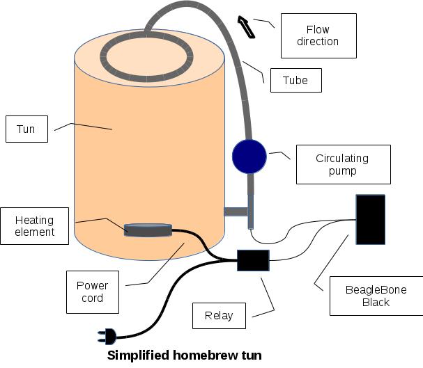
Figure 1. Simplified Homebrew Tun
Many of our beers have a starting point between 45°C–55°C. In this temperature range, we are preparing the proteins in the malt for the later process of extracting sugars out of the malt. The optimal temperature for the beta and alpha enzymes that convert starch to sugars is between 63°C–68°C. So after the protein stop in the 50°C range, we have to raise the temperature in the mash. But unfortunately, too much heat will burn some of the particles floating in the mash onto the heater in the bottom of the tun, resulting in a bad taste and difficulty getting the heat from the heating element into the mash. We have determined empirically that from 59°C–60°C we can apply full power. To finish the process, the temperature is raised to 78°C to stop the enzymes from working.
So, we need a way to control the amount of power fed into the heating element. What is more natural than to use a BeagleBone Black to control the rate of energy burned in the heater through a Pulse Width Modulated (PWM) controller already built in to the BeagleBone? The PWM will produce a pulse of varying width, turning a relay on and off in controlled intervals, thereby controlling the amount of power fed into the heater. If the relay is closed for 2 seconds and off for 8 seconds, 2/8 * 1800 W = 450W is fed into the heater. Well, to be honest, this problem could be solved using a simple 555 chip and a potentiometer, but since we are programmers, we tend to pull out the tools we love, even when it's overkill.
A side benefit from setting up a BeagleBone is the ability to log temperatures during the whole brew process. This is handy for evaluating the beer when adjustments to the recipe, which include the processing, are discussed. Previously, we noted temperatures and times on a piece of paper a few times during the brew process—when we remembered to do it. Another benefit is that the whole thing can be controlled from a Web page.
I've already mentioned the requirements, and from there, you can extract that we need a controlling functionality that will read the temperature in the mash when it leaves the bottom of the tun. Based on the temperature read, it will set the period time of the output PWM. Also, we need a database enabling us to log the collected data during the brew process. Now, a database also could archive the recipes or at least the part of the recipes that is about temperatures and time. Finally, I also mentioned having a Web page. Data comes from the database, but how do we serve the data to the Web page? Because I also wanted to show the state of the controller on the Web page, I embedded a Websocket server into the application. This led (after a few iterations) to the software architecture diagram shown in Figure 2. Add to the architecture diagram a Web client program—for example, Firefox that loads and executes the JavaScript code embedded in the Web page. However, the database and Web page are beyond the scope of this article; I may cover them in a future article.
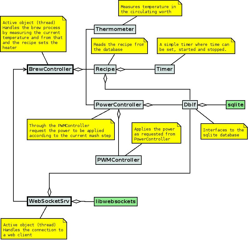
Figure 2. Brew Controller Software Architecture
I decided to develop in C++, but I could have used any programming language. In fact, I did start developing a prototype in BoneScript, a dialect of JavaScript that builds on Node.js, which is programmed in JavaScript. It worked quite well, but I was unsure whether I could trust it to be stable in the long run. I noticed during my tests that the BoneScript program had some delays a few arbitrary times and hiccups I couldn't explain. A program, where I know all details and that is compiled, is by far the most efficient, and once tested and debugged, I can trust this one to run for long time. And, now I also have several different examples of the same solution to show my students and discuss with them.
In order to prepare for developing the software that fulfills the requirements, a few things needed to be set up and configured:
Cross compilation.
Remote debugging.
Setting up a temperature sensor.
Setting up the PWM output.
A log utility.
Threading.
Cross Compilation:
I prefer to develop using Eclipse when it is a larger project that runs over some time. There is no problem when developing small and quick solutions directly on the BeagleBone, but when complexity increases, the help that an integrated development environment provides levels out some of the complexity. Can you install Eclipse on the BeagleBone? Yes, it should be possible, but since the storage on the BeagleBone is Flash-based, I prefer to run Eclipse on my laptop. A lot of writing to files can wear out the Flash memory on the BeagleBone.
The BeagleBone is built using an ARM CPU architecture, and most desktops and laptops are Intel CPU architectures. This means we need to install a cross compiler on the laptop. A cross compiler is a compiler that produces executable code for another CPU architecture than what it executes on. In this case, the compiler executes on an Intel CPU but produces code for an ARM CPU.
I run Fedora Linux and have been doing so ever since the Fedora Project was launched. I couldn't find a suitable cross compiler in the repositories for Fedora, however. So, after some searching, eventually I found that Linaro.org maintains a suitable compiler suite that I could install. If you're following along, you should download a stable release from the repository. This is the one I downloaded: releases.linaro.org/14.11/components/toolchain/binaries/arm-linux-gnueabihf/gcc-linaro-4.9-2014.11-x86_64_arm-linux-gnueabihf.tar.xz. There might be fresher copies by the time you read this. Take a look at releases.linaro.org/14.11/components/toolchain/binaries, and be sure to download a gnueabihf version—the compiler that produces code for a hard floating-point unit.
I keep my downloaded tools, like compilers and Eclipses, in the /opt directory, so I unpacked the tarball in a directory I named toolchains. In this directory, you can make a symbolic link to the very long directory name you will get out of the tarball. This makes it easier when configuring a project in Eclipse. I made a symbolic link called gnueabihf, which is far easier to remember than gcc-linaro-4.9-2014.11-x86_64_arm-linux-gnueabihf. And if I update the compiler at a later time, I can just remove the link and create a new one pointing to the newer compiler. I don't have to change anything in Eclipse.
In Eclipse, you have to select the Cross GCC choice in the toolchain section of the New Project dialog. In the next dialog, enter “arm-linux-gnueabihf-” in the Cross Compiler Prefix entry. If you look into the directory where you stored the cross compiler, you will find that almost all binaries are prefixed with this. So the gcc is really arm-linux-gnueabihf-gcc. In the cross compiler path, enter the path to where you installed the cross compiler—for example, /opt/toolchains/gnueabihf/bin. Now Eclipse knows how to produce executables that will run on the BBB.
Remote Debugging:
Regardless of how experienced we are, bugs tend to creep into our code making programs not work as expected. So the ability to debug is mandatory—well, for me at least, but I also do have only 30+ years of programming experience. Luckily, it is possible to set up Eclipse so you can execute the freshly compiled program over on the BeagleBone under debugger control.
Included with the gnueabihf package is a gdbserver that can cooperate with Eclipse or, more precisely, with gdb the debugger. The gdbserver that comes with the BeagleBone by default does not cooperate well with Eclipse. So, you have to copy the gdbserver to the BeagleBone:
scp /opt/gnueabihf/bin/gdbserver <username>@<your BBB IP>:~/
If you just use the USB-created network interface, the address is 192.168.7.2. I have set up a Wi-Fi dongle on my BBB, so my address is different.
The next task is to configure Eclipse to perform remote debugging. Because this is a rather long procedure, I have collected it on a page at klaus.ede.hih.au.dk/index.php/BBB_Remote_Debugging. I made it for my students to follow, so readers of Linux Journal also should be able to follow these instructions.
Now we're ready to start programming. My typical practise, when attacking something I don't know anything or at least not much about, is to create small projects where I isolate the particular problem I am dealing with. One of the first things was measuring the temperature. I had a DS18B20 1-Wire temperature sensor. The sensor is embedded in a metal cap, so it is fine in food production environments. You easily can find them on eBay or similar sites.
Getting the Temperature:
I've never worked with 1-Wire devices (I just knew they existed), so I had to do some reading to understand the device, but it is rather simple. Each device on the 1-Wire bus has a unique address. Now for the purpose of this article and the project, you don't need to have a full understanding of the 1-Wire devices, because the Debian Linux that comes with the BeagleBone has drivers for 1-Wire devices. So, there's no need to develop a device driver ourselves.
The BeagleBone uses the Flattened Device Tree (FDT), like many modern Linux distros for embedded systems running on an ARM architecture. The ARM CPU that is on the BeagleBone has an electronic pin multiplexer (a kind of switchboard) built in, enabling you to connect pins from the outside world to a specific internal device—for example, GPIO or PWM. The FDT will help you set this up, and it tells the kernel which type of interface it is enabling, so the kernel can use a suitable driver to service the pin. For more information on the FDT, see elinux.org/Device_Tree.
Basically, the FDT works by having a text file with the specification of the connection you want to enable. This specification file is compiled into binary format. You may be interested in a generator for DTS files, because it takes a lot of research and thought to put together a DTS. I stumbled upon this site: kilobaser.com/blog/2014-07-28-beaglebone-black-devicetreeoverlay-generator#dtogenerator, which I find helpful in cooperation with the technical specification of the BeagleBone (which is at https://github.com/CircuitCo/BeagleBone-Black/blob/master/BBB_SRM.pdf?raw=true).
By looking in the technical specification in table 13, I could see that pin 12 on the P9 header could be connected to a GPIO pin. After some testing, I managed to put together a device tree file that enabled me to connect the DS18B20 to P9 pin 12:
/dts-v1/;
/plugin/;

/ {
    compatible = "ti,beaglebone", "ti,beaglebone-black";
    part-number = "DS1820";
    version = "00A0";

    exclusive-use = "P9.12";

    fragment@0 {
        target = <&am33xx_pinmux>;
        __overlay__ {
             ds1820_pins: pinmux_ds1820_pins {
                 pinctrl-single,pins =  <0x78 0x37>;
             };
        };
    };

    fragment@1 {
        target = <&ocp>;
        __overlay__ {
            onewire@0 {
                status          = "okay";
                compatible      = "w1-gpio";
                pinctrl-names   = "default";
                pinctrl-0       = <&ds1820_pins>;
                gpios           = <&gpio2 28 0>;
            };
        };
    };
};
Save the specification in a file called DS18B20-00A0.dts, and compile it into the binary format using this command:
root@beaglebone:~# dtc -O dtb -o /lib/firmware/DS1820-00A0.dtbo
 ↪-b 0 -@ DS1820-00A0.dts
dtc is a Device Tree Compiler. In the above command, it's instructed to output in the dtb format (-O) into a file in the /lib/firmware directory (-o). The -b sets the boot CPU (here 0) and the -@ means to use symbols, and finally, the input file is specified.
To enable this part of the device tree, issue this command:
root@beaglebone:~# echo DS1820 >
 ↪/sys/devices/bone_capemgr.*/slots
If you don't get any errors, run ls -la in the /sys/bus/w1/devices directory:
root@beaglebone:~# ls -la /sys/bus/w1/devices
total 0
drwxr-xr-x 2 root root 0 Jan  1  2000 .
drwxr-xr-x 4 root root 0 Jan  1  2000 ..
lrwxrwxrwx 1 root root 0 Aug 30 17:32 28-000005a7ce64 ->
 ↪../../../devices/w1_bus_master1/28-000005a7ce64
lrwxrwxrwx 1 root root 0 Aug 30 17:32 w1_bus_master1 ->
 ↪../../../devices/w1_bus_master1
root@beaglebone:/lib/firmware#
The 28-000005a7ce64 file (a symbolic link) is the thermometer. Each 1-Wire device has a unique ID, so it will be identified by a pattern like 28-00000nnnnnnn, where nnnnnnn is the unique address.
A quick test to see if the DS18B20 is working correctly can be done by changing the device address in this Python script to suit your configuration:
import time

w1="/sys/bus/w1/devices/28-000005a7ce64/w1_slave"

while True:
    raw = open(w1, "r").read()
    print "Temperature is "+str(float(raw.split("t=")
↪[-1])/1000)+" degrees"
    time.sleep(1)
If you want to have the DS18B20 enabled at every boot, prepare a file in /etc/init.d, and call it enable-DS18B20 or something similar. Put this into the file:
#! /bin/sh

### BEGIN INIT INFO
# Provides: enable-DS18B20
# Required-Start: $all
# Required-Stop: $all
# Default-Start: 2 3 4 5
# Default-Stop: 0 1 6
# Short-Description: Enables the DS18B20 1-wire
 ↪on P9 pin 12
# Description: Connecting the 1-wire driver to
 ↪the P9 pin 12
### END INIT INFO
case "$1" in
        start)
            echo "Enabling 1-Wire DS18B20 on P9 Pin 12"
            echo DS1820 > /sys/devices/bone_capemgr.9/slots
        ;;
        stop)
            #no-op
        ;;
        *)
            #no-op
        ;;
esac

exit 0
After creating the file, execute:
root@beaglebone:/etc/init.d# chmod 755 enable-DS18B20
root@beaglebone:/etc/init.d# update-rc.d enable-DS18B20
 ↪defaults
Try to reboot your system and check that the device is enabled as expected.
Setting Up the PWM Controller:
As I mentioned earlier, a way of controlling the amount of power supplied to the heater is to use a PWM signal to control a relay. If you turn it on for one-third of the time and off for two-thirds, the applied heat is only one-third of the usual amount of heat when running switched on all the time. This can prevent having particles in the brew burn onto the heater. See Figure 3 for an example PWM signal output. Here I have set the period time to be approximately one second and the “on” time to be approximately 20% of the period time.
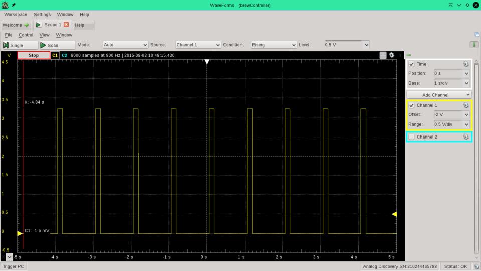
Figure 3. PWM Signal Output
As for the 1-Wire, you also need a configuration on the device tree in order to gain access to the PWM controllers on the board and to connect it to a suitable pin. If you consult the BeagleBone's technical specification, you will find that P9,14 connects to a PWM controller. So, jump to the on-line device tree generator and select P9_14 in the “Select Pin” box. Then select “Fast Slew” in the “Slew” box, “Pullup” in “Pullup/Down”, and finally, in MuxMode “Mode6: ehrpwm1A”, and you will get a device tree file like this:
 *
 * Copyright (C) 2013 CircuitCo
 * Copyright (C) 2013 Texas Instruments
 *
 * This program is free software; you can redistribute
 * it and/or modify it under the terms of the GNU
 * General Public License version 2 as
 * published by the Free Software Foundation.
 *
 * This is a template-generated file from BoneScript
 */
/dts-v1/;
/plugin/;

/ {
   compatible = "ti,beaglebone", "ti,beaglebone-black";

  /* identification */
  part-number = "BS_PWM_P9_14_0x16";

  /* state the resources this cape uses */
  exclusive-use =
          /* the pin header uses */
          "P9.14",
          /* the hardware IP uses */
          "ehrpwm1A";

  fragment@0 {
    target = <&am33xx_pinmux>;
    __overlay__ {
      bs_pwm_P9_14_0x16: pinmux_bs_pwm_P9_14_0x16 {
              pinctrl-single,pins = <0x048 0x16>;
      };
    };
  };

  fragment@1 {
    target = <&ocp>;
    __overlay__ {
      bs_pwm_test_P9_14 {
              compatible      = "pwm_test";
              pwms            = <&ehrpwm1 0 1000000000 1>;
              pwm-names       = "PWM_P9_14";

              pinctrl-names   = "default";
              pinctrl-0       = <&bs_pwm_P9_14_0x16>;

              enabled         = <1>;
              duty            = <0>;
              status          = "okay";
      };
  };
  };
};
If you want the polarity initially set to 0, change the 1 to 0 in the pwms line so it looks like this:
pwms = <&ehrpwm1 0 500000 0>;
Again, you need to compile it from text format to the binary format readable by the kernel:
root@beaglebone:~# dtc -O dtb -o
 ↪/lib/firmware/bspwm_P9_14_16-00A0.dtbo
 ↪-b 0 -@ bspwm_P9_14_16-00A0.dts
To check that you can create a PWM device file, execute these commands:
root@beaglebone~# echo "am33xx_pwm" >
 ↪/sys/devices/bone_capemgr.9/slots
root@beaglebone~# echo bspwm_P9_14_16 >
 ↪/sys/devices/bone_capemgr.9/slots
If no errors are shown, take a look in the device directory:
root@beaglebone:~# ls -al
 ↪/sys/devices/ocp.3/bs_pwm_test_P9_14.16/
total 0
drwxr-xr-x  3 root root    0 Jan  1  2000 .
drwxr-xr-x 42 root root    0 Jan  1  2000 ..
lrwxrwxrwx  1 root root    0 Sep 19 11:40 driver ->
 ↪../../../bus/platform/drivers/pwm_test
-rw-rw-rw-  1 root root 4096 Mar  1  2015 duty
-r--r--r--  1 root root 4096 Sep 19 11:40 modalias
-rw-rw-rw-  1 root root 4096 Mar  1  2015 period
-rw-rw-rw-  1 root root 4096 Mar  1  2015 polarity
drwxr-xr-x  2 root root    0 Sep 19 11:40 power
-rw-------  1 root root 4096 Sep 19 11:40 run
lrwxrwxrwx  1 root root    0 Jan  1  2000 subsystem ->
 ↪../../../bus/platform
-rw-r--r--  1 root root 4096 Jan  1  2000 uevent
The files of interest are “polarity”, “period” and “duty”. The polarity controls whether the controller outputs 0 or 1 when turned off. The period, as the name indicates, controls the period time—that is, for what length of time is a complete cycle in the controller. The period time is set in nanoseconds. Finally, the duty controls the amount of time that the signal from the PWM controller is active. The duty is set in percentages—for example, for 50%, you would write 0.5 to the duty file.
And as for the temperature sensor, an automatic start at boot would be handy, so create this file in /etc/init.d/enable-pwm with this content:
#! /bin/sh

### BEGIN INIT INFO
# Provides: enable-pwm
# Required-Start: $all
# Required-Stop: $all
# Default-Start: 2 3 4 5
# Default-Stop: 0 1 6
# Short-Description: Enables the PWM chips and
# connects it through the pinmux
# Description: Connecting the pwm output through
# the pinmux and enables the PWM chip on board
### END INIT INFO
case "$1" in
  start)
      echo "Enabling PWM on P9 Pin 14"
      grep -q am33xx_pwm /sys/devices/bone_capemgr.9/slots ||
       ↪echo "am33xx_pwm" \
          >  /sys/devices/bone_capemgr.9/slots
          echo bspwm_P9_14_16 > /sys/devices/bone_capemgr.9/slots
  ;;
  stop)
          #no-op
  ;;
  *)
          #no-op
  ;;
esac

exit 0
Reboot your BeagleBone and check that you get the PWM device files created as shown above.
Now you're ready to develop a program that will measure the temperature, and based on a recipe, calculate the necessary power to apply to the heater.
A Simple Log Utility:
When developing a program, it's often necessary to log different values from the program, especially when you have several threads running. Nothing happens at the time you would expect it to—this is the nature of threading. Therefore, I often print out to the console or log to a file, which lets me follow the progress of the program.
In this project, I started printing to the console but switched to logging to a logfile. I searched the Internet and ran across this site: www.infernodevelopment.com/c-log-file-class-forget-debuggers.
The header looks like this:
#include <fstream>

using namespace std;

class Log
{
  public:
    Log (const char* filename);
    ~Log ( );
    void Write (const char* logline, ...);
    private:
    ofstream m_stream;
};
And the implementation is simple:
#include "Log.h"
#include <stdarg.h>

Log::Log (const char* filename)
{
  m_stream.open (filename);
}

Log::~Log ( )
{
  m_stream.close ();
}

void Log::Write (const char* logline, ...)
{
  va_list argList;
  char cbuffer[1024];
  va_start(argList, logline);
  vsnprintf (cbuffer, 1024, logline, argList);
  va_end(argList);
  m_stream << cbuffer << endl;
}
This version allows me to log using the sprintf conversion specifiers—for example, %f for floats. I use it like this:
log->Write("PowerController: INFUSION POWER: \
  PWM set to      %f\n", maxPWM);
Notice here, that I use %f and pass a float value, which will be logged just like (s)printf would convert the float to a string of digits. This is due to the varadic declaration of the Write function.
When you want to see the log while the program runs, open another SSH connection to the BeagleBone and run:
root@beaglebone:~# tail -f <logfilename>
where you, of course, need to change <logfilename> to match your current log file.
Threading:
I know that C++ ISO standard 2011 (or just C++11) allows you to create threads in C++ directly, but prior to that, I needed a way to make classes (or a function in a class) into a thread.
I found an example class on StackOverflow that I have been using ever since. So why learn something new, when you know how to do it? We are all a bit lazy now and then, aren't we? Here it is:
#include <pthread.h>
#include <cstdlib>

class Threadable
{
public:
  Threadable()
  {
    _thread = (pthread_t)NULL;
  }
  virtual ~Threadable()
  {/* empty */
  }

  /** Returns true if the thread was successfully
   started, false if there was an error starting
   the thread */
  bool StartInternalThread()
  {
    return (pthread_create(&_thread, NULL,
     ↪InternalThreadEntryFunc, this) == 0);
  }

  /** Will not return until the internal thread has exited. */
  void WaitForInternalThreadToExit()
  {
    (void) pthread_join(_thread, NULL);
  }
  pthread_t GetThreadID () { return _thread; }

protected:
  /** Implement this method in your subclass with
  the code you want your thread to run. */
  virtual void InternalThreadEntry() = 0;

private:
  static void * InternalThreadEntryFunc(void * This)
  {
    ((Threadable *) This)->InternalThreadEntry();
    return NULL;
  }

  pthread_t _thread;
};
This is a virtual base class that you can't create instances of directly, but you will inherit from it in a new sub-class.
So, for instance, my BrewController class begins like this:
class BrewController: public Threadable
{
  public:
    BrewController ( );
    virtual ~BrewController ( );
    void InternalThreadEntry ( );
...
The InternalThreadEntry ( ) is the thread function for this class. So you will just have to fill in the code that composes the thread. The rest of the methods in the class are helper functions in one way or another.
In order to control the heater, we need to measure the temperature in the mash. Having a representation of the temperature, it is a matter of comparing the current temperature with the desired temperature for the current step in the recipe. We use a PID controller to calculate the amount of power needed, but due to our experience with particles in the mash burning onto the heater, it may be necessary to limit the power. So the PID controller may call for full power, but the applied power is limited.
Measuring the Temperature:
The first thing to do in the program is to locate the thermometer or the temperature sensor. I want the program to locate any DS18B20 attached to the BeagleBone. As mentioned earlier, the 1-Wire devices all have unique addresses. I currently have five or six DS18B20 thermometers on hand, so I designed the software so that I can attach any of my thermometers to the BeagleBone, and the program will locate it and start using it.
This code snippet does the trick (it is from a class I call Thermometer):
int Thermometer::locateThermometer()
{
  string initialDir = "/sys/bus/w1/devices/";
  string regExpr = "28-00000";
  string dir;

  // Open directory
  DIR *dp = opendir(initialDir.c_str());
  if (!dp)
  {
    exit (EXIT_FAILURE);
  }
  struct dirent *dirp;

  // Loop through the directory entries
  while ((dirp = readdir(dp)) != NULL)
  {
    std::size_t found = \
      string(dirp->d_name).find(regExpr);
    if (found != std::string::npos)
    {
      // We found one entry that matches
      oneWireDir = initialDir + string(dirp->d_name)\
        + string("/w1_slave");
      // Nicely close the directory again
      (void) closedir(dp);
      return 0;
    }
  }
  exit(EXIT_FAILURE);
}
oneWireDir is a class variable where I keep the directory and file from which I can read the temperature sensor.
The output from a DS18B20 is made up of different information. Take a look at the output below:
root@beaglebone:/sys/bus/w1/devices/28-000005a7ce64# cat w1_slave
85 01 4b 46 7f ff 0b 10 5f : crc=5f YES
85 01 4b 46 7f ff 0b 10 5f t=24312
root@beaglebone:/sys/bus/w1/devices/28-000005a7ce64#
The first line is of no interest to us. The second line shows that the temperature t is 24.312°C. From this, we learn that it is just a matter of reading the w1_slave file and grabbing the temperature from the output. I have designed this function to do the task:
int Thermometer::readTemperature()
{
  int fd;
  int res;

  // Open the OneWire thermometer file
  fd = open(oneWireDir.c_str(), O_RDONLY);
  if(!fd)
  {
    return -1;
  }
  char buf[256];
  // Read from it
  res = read(fd, buf, sizeof(buf));
  if (res < 0)
  {
    close (fd);
    return -1;
  }
  // Retrieve current temperature from device
  if (res > 0)
  {
    std::size_t found = string(buf).rfind('=');
    if (found != std::string::npos)
    {
      curTemp = atof((const char *) \
                &buf[found+1]) / 1000;
    }
    else
    {
      close(fd);
      return -1;
    }
  }
  close (fd);
  // Call calc average temperature
  return calcAvgTemp();
}
The file is opened and read, and because there are two = characters in the buffer, I perform a reverse search (from the end of the buffer rather than from the beginning) in the buffer for =. When the = is located, I convert the ASCII text to a float using atof and scale it with 1,000 since there are no decimal points in the readout from the sensor.
The next thing to do is to calculate the average temperature. I keep the last five samples in an array in order to calculate an average temperature. The reason for this is that I occasionally saw some spurious measurements where the temperature was a bit off. The averaging will smooth this out:
int Thermometer::calcAvgTemp()
{
  float t = avgTemp - curTemp;
  if ((t < -20 || t > 20) && tempSamples.size() > 4)
  {
    // Skip this measurement - it's way out of range.
    log->Write("Skipped this temperature: %f, \
                t = %d\n", curTemp, t);
    return -1;
  }
  if (tempSamples.size() > maxSamples)
  {
    // Get rid of first element
    tempSamples.erase(tempSamples.begin());
  }
  tempSamples.push_back(curTemp);
  t = 0;
  for (int i = 0; i < (int)tempSamples.size(); i++)
  {
    t += tempSamples[i];
  }
  avgTemp = t / tempSamples.size();
  return 0;
}
maxSamples currently is set to 5. As you can see, if the vector that holds the samples is filled, I drop measurements that are 20°C off the average. If the vector is not filled, I add the sample to be included—it is needed when starting the measurements.
From this point, we just need to set up, somewhere else, a timed job that calls the readTemperature() function. I have set it up to read every tenth second. With a mass of approximately 30kg, it is a relatively slow process.
A PID Controller:
What is a PID controller? It is a proportional-integral-derivative controller. From that, you can see that it is a controller that reacts proportionally on the measured input compared to the set point (the desired value), and it accumulates the historic development of the controlled using an integral function, and finally, it tries to predict the future in the derivative part. That was a big mouthful. Let's take this one step at a time.
See the diagram of a PID controller in Figure 4 or expressed as a formula in Figure 5.
Figure 4. PID en updated feedback by TravTigerEE—Own work. Licensed under CC BY-SA 3.0 via Commons.
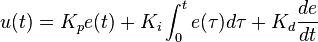
Figure 5. PID Formula
Our “plant” (as shown in Figure 4) is the brew tun. We measure, like in this project, a temperature, and elsewhere, we have a desired temperature we want to keep for a while. The difference between the measured and desired temperature is called the error—e(t) in the Figure.
The error signal is fed into the proportional, integral and derivative part of the controller.
The Proportional Controller:
If the measured temperature is lower than the desired, we can fire up the heater to raise the temperature. If it is higher, we can do nothing in this setup but wait for it to cool down a little.
The amount of power that we'll apply to the heater is controlled by the error signal. If the error is small, a small amount of power is applied, and if it is large, we apply more power to the heater. By having a factor (Kp) to multiply with the error, we can amplify the error, or if the factor is below 1, attenuate the impact of the error. The proportional part of the PID controller tends to overreact—that is, the temperature overshoots the desired temperature by quite an amount. This is not desired in a process where we are seeking to give our enzymes ideal temperatures to work in. And if enzymes get too warm, they will denature—that is, die! The derivative part will compensate for this to some degree.
The Integral Controller:
The integral part of the controller sums or accumulates the error over time. This part can suppress the proportional part, but with the cost of being slower to reach the desired set point.
The Derivative Controller:
This part looks into the future, so to speak. It compares the previous measurement with the current one in order to predict the future state of the plant. This results in a quicker raise to the desired set point, but it also will back off when nearing the set point, leaving the fine-tuning to the P and I parts.
For further details, take a look at this fine article by Wess Scott: m.eet.com/media/1112634/f-wescot.pdf, or see this page on Wikipedia: https://en.wikipedia.org/wiki/PID_controller.
The PID Code:
It's rather easy to implement a PID controller in software:
// The PID Controller
float processVal = curTemp;

// The Proportional part
float error = setPoint - processVal;
float pTerm = pGain * error;

// The Integral part
iState = iState + error;
float iTerm = iState * iGain;

// The Derivative part
float dTerm = (dState - processVal) * dGain;
dState = processVal;

// Scaling to fit
float pwr = (pTerm + iTerm + dTerm) / 10;
The factors (Kp, Ki and Kd) that I currently use are set to:
pGain = 5.0;   // Kp
iGain = 0.025; // Ki
dGain = 30.0;  // Kd
I let the proportional and derivative parts have quite a large impact, and the integral part is dampened quite a bit.
So after getting the PID controller set and working as desired (although some fine-tuning can be done on the Kn parameters in order to find the optimal for my set up), it's time to turn to the PowerController.
Controlling the Heater:
The output from the Thermometer class is fed into the PowerController. This class uses the PID controller to calculate the amount of power to apply.
As mentioned before, I had to limit the amount of power applied even if the PID controller called for more. The reason is that below 57°C–59°C, we have determined that if we apply one-third of the available power, we will not cause anything to burn onto the heater. Therefore, I have set some limits, regardless of how much power the PID controller calls for.
But hey, what about infusion? Infusion is the point in time where we add the malt to the preheated water. It's also called the strike temperature. The colder malt mixes with the water and cools it a little. Therefore, the infusion temperature can be calculated from the mass of water and malt using the amount of them both and the temperature of the malt (Figure 6). So if the desired infusion (or strike) temperature is 55°C, the amount of water is 19 liters, and the 7kg of malt is 14°C, we can calculate that the water should be preheated to 59.8°C before adding the malt. After a short while, it'll find its rest at 55°C.
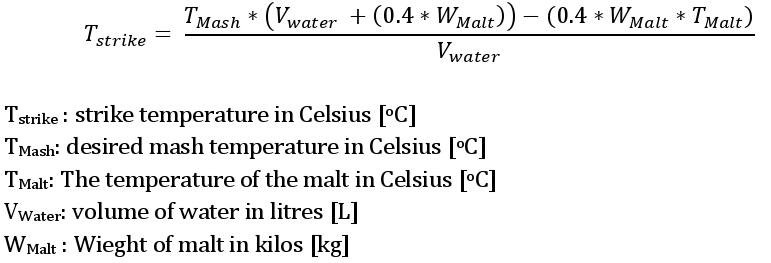
Figure 6. Strike Temperature Calculation
In order to get ready for brewing as quickly as possible, we can heat the water with full power until we add the malt. So we need to know the different steps of the mashing process, which is kept in a database (more about that later). From that, we get the set point.
I have put the maximum temperature ranges into a two-dimensional array of floats:
tempPwrRange[0][0] = 57;     // Below this temp. use
tempPwrRange[0][1] = 0.333;  // this amount of pwr
tempPwrRange[1][0] = 60;     // Below this temp. use
tempPwrRange[1][1] = 0.666;  // this amount of pwr
tempPwrRange[2][0] = 102;    // Below this temp. use
tempPwrRange[2][1] = 1.0;    // this amount of pwr
Then, it's simple to compare against the current temperature and find the maximum amount of power that may be applied:
// Locate the temperature range to operate within
// Use the current temperature measured to retrieve
// the maxPwr
for (int i = 0; i < 3; i++)
{
  limitTemp = tempPwrRange[i][0];
  maxPwr = tempPwrRange[i][1];
  if (curTemp > limitTemp)
  {
    continue;
  }
}
After having the PID controller calculate the desired power, it is left to the setPwrLvl function to find what can be set according to the current step in the recipe from where we have derived the maxPwr:
float PowerController::setPwrLvl (float pwr,
                                  float maxPwr)
{
  // The PWM operates with a high granularity,
  // hence we have to scale the pwr

  // Corrects the duty cycle when applied to the PWM
  const long long Factor = 999000000;
  log->Write("PowerController: maxPwr is set to %f",\
             maxPwr);

  // If the requested pwr is less that 0
  // we set it to 0
  if (pwr < 0)
  {
    // Set PWM to 0
    if (pwm.setDutyCycle (0) == 0)
    {
      log->Write("PowerController: PWM set to 0\n");
    }
    else
    {
      log->Write("PowerController: ERROR: \
                 PWM not set! (pwr<0)\n" );
    }
    return 0.0;
  }

  // If we are in the infusion step it is allowed to use max pwr
  if (infusion)
  {
    if (pwm.setDutyCycle (maxPWM) == 0)
    {
      log->Write("PowerController: INFUSION POWER:\
                  PWM set to      %f\n", maxPWM);
    }
    else
    {
      log->Write("PowerController: ERROR: PWM not\
                  set! value: %f\n", maxPWM);
    }
    return 1.0;
  }

  // If the pwr is less than the maxPwr allowed
  // use the requested pwr
  if (pwr < maxPwr)
  {
    // Set PWM to pwr
    if (pwm.setDutyCycle (pwr * Factor) == 0)
    {
      log->Write("PowerController: PWM set to \
                  %f\n", pwr * Factor);
    }
    else
    {
      log->Write("PowerController: ERROR: PWM not \ set!\n");
    }
    return pwr;
  }

  // Otherwise use the maximum power, i.e. 100%
  else
  {
    // Set PWM to the maxPwr
    if (pwm.setDutyCycle (maxPwr * Factor) == 0)
    {
      log->Write("PowerController: PWM set to \
                  %f\b", maxPwr * Factor);
    }
    else
    {
      log->Write("PowerController: ERROR: PWM not \
                  set!\n");
    }
    return maxPwr;
  }
  return 0.0;
}
The setDutyCycle function actually writes to the PWM file that represents the PWM controller on board:
int PWMController::setDutyCycle(long long duty)
{
  string dir;

  dir = initialDir + "/duty";

  // Open the file representing the PWM controller
  int f = open(dir.c_str(), O_WRONLY);
  if (f < 0)
  {
    log->Write("ERROR Opening file %s with this \
                error: %s\n",
                dir.c_str(),
                strerror( errno ));
    return -1;
  }

  // Write the requested duty cycle to the file
  char str[100];
  sprintf(str, "%lld", duty);
  size_t res = write (f, str, strlen(str));
  close (f);

  // Handle errors
  if (res != strlen (str))
  {
    log->Write("ERROR Opening file %s with this \
                error: %s\n",
                dir.c_str(),
                strerror( errno ));
    return -1;
  }
  return 0;
}
Yes, I know—I am a C hacker (mis)using the fine C++ language with file operations in plain C code. But, so it is! What comes easiest to the fingers over the keyboard is what comes in the code—sometimes I think there may not be a brain involved at all. But otherwise, it's straightforward code.
This concludes the measuring of the temperature and controlling the power output. In a future article, I'll look into adding an SQLite database to the brewController program. In order to service a Web page, we also need a WebSocket server, so I will introduce that as well.
The database has two purposes: storing recipe details for the mash process and continuous logging of data produced during a brew.
The WebSocket server is the interface to the Web page from where we can monitor and control the brewing process. So I also will dive into a relatively complex Web page with a lot of JavaScript code to control the graphs and retrieval of data from the WebSocket server, which will look up in the database for the correct data to serve.
Finally, I'll write about how to dæmonise the brewController and make it start automatically when the BeagleBone is powered.
All the code will be open-sourced when it has proven to control a few brews this autumn. If you are in a hurry, send me an e-mail and I will send you the code.
